Unvented natural gas fireplace, Installation, Continued – Vanguard Heating VSGF28NTC User Manual
Page 10: Installing gas piping to fireplace location
10
107157
UNVENTED NATURAL GAS FIREPLACE
®
For more information, visit www.desatech.com
INSTALLING GAS PIPING TO
FIREPLACE LOCATION
Installation Items Needed
Before installing fireplace, make sure you
have the items listed below.
• piping (check local codes)
• sealant (resistant to propane/LP gas)
• equipment shutoff valve *
• test gauge connection *
• sediment trap
• tee joint
• pipe wrench
* A CSA/AGA. design-certified equipment
shutoff valve with 1/8" NPT tap is an accept-
able alternative to test gauge connection. Pur-
chase the optional CSA/AGA. design-certi-
fied equipment shutoff valve from your dealer.
See Accessories, pages 22 and 23.
WARNING: A qualified ser-
vice person must connect fire-
place to gas supply. Follow all
local codes.
WARNING: Never connect
fireplace to private (non-utility)
gas wells. This gas is commonly
known as wellhead gas.
CAUTION: Use only new,
black iron or steel pipe. Inter-
nally-tinned copper tubing may
be used in certain areas. Check
your local codes. Use pipe of 1/2"
diameter or greater to allow
proper gas volume to fireplace. If
pipe is too small, undue loss of
pressure will occur.
INSTALLATION
Continued
Mantel Clearances for Built-In
Installation
If placing mantel above built-in fireplace,
you must meet minimum clearance between
mantel shelf and top of fireplace opening.
If your installation does not meet the below
minimum clearances, you must:
• raise the mantel to an acceptable height,
OR
• remove the mantel.
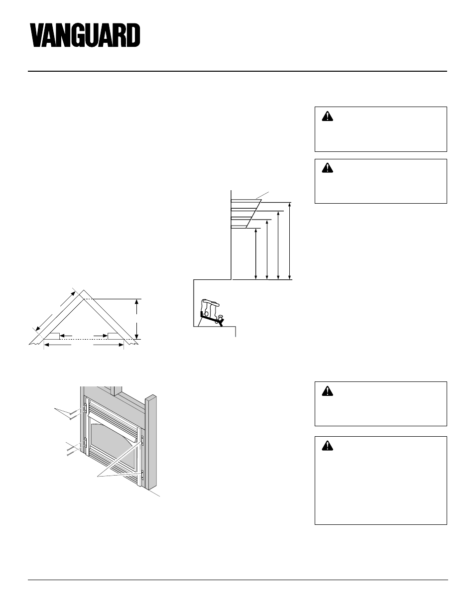
Figure 14 - Rough Opening for Installing
in Corner
Figure 15 - Attaching Fireplace to Wall
Studs
Figure 16 - Minimum Mantel Clearances
for Built-In Installation
Mantel
Shelf
Note:
All Vertical
measurements
are from top of
fireplace
opening to
bottom of
mantel shelf.
Nailing
Flanges
Nails or
Wood
Screws
4.
Carefully set fireplace in front of rough
opening with back of fireplace inside
wall opening.
5.
Carefully insert fireplace into rough
opening.
6.
Attach flexible gas line to gas supply.
See Connecting Fireplace to Gas Sup-
ply, page 11.
7.
Attach fireplace to wall studs using
nails or wood screws through holes in
nailing flange (see Figure 15).
8.
Check all gas connections for leaks. See
Checking Gas Connections, page 12.
9.
Plug electrical cord into electrical out-
let installed in step 2, page 9.
10. Install brass trim after final finishing
and/or painting of wall (see Figure 7,
page 8).
WARNING: This appliance re-
quires a 1/2" NPT (National Pipe
Thread) inlet connection to the
pressure regulator.
39 3/8"
27 7/8"
55 5/8"
35 1/2"
13"
16"
19"
21"
2
1/2
"
6"
8"
10"