Connecting suppl – Utica Gas-fired Boiler User Manual
Page 7
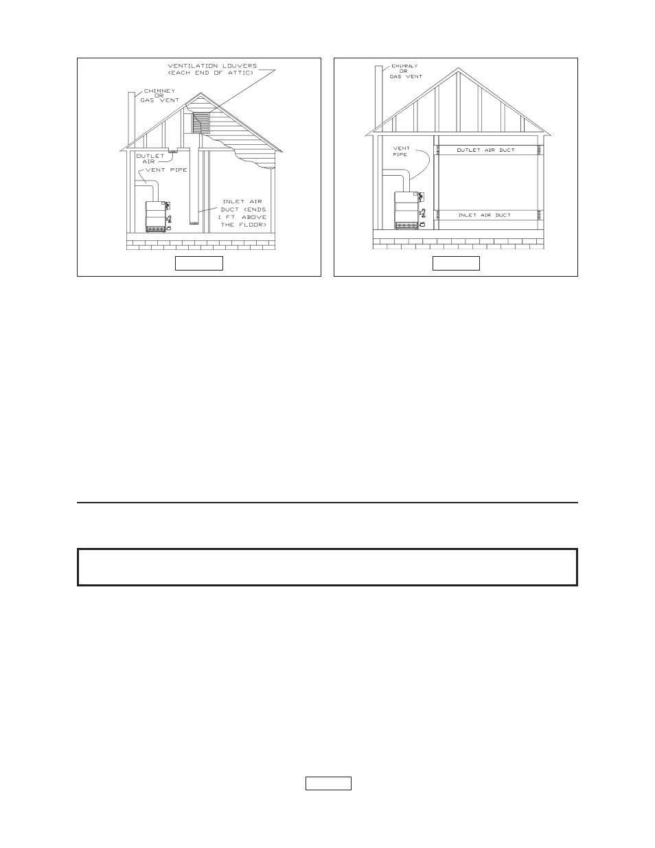
FIGURE 3
FIGURE 4
shall be permitted where the equipment has clearances of at least 1 inch from the sides, 1
inch from the back, and 6 inches from the front of the boiler. The opening shall directly
communicate with the outdoors or shall communicate through a vertical or horizontal duct to
the outdoors or spaces (crawl or attic) that freely communicate with the outdoors. The
openings must have a minimum free area of 1 square inch per 3000 Btu per hour of the total
input rating of all equipment located in the enclosure. The free area must be no less than the
sum of the areas of all vent connectors in the confined space.
6. In calculating free area using louvers, grilles or screens for the above, consideration shall
be given to their blocking effect. Screens used shall not be smaller than 1/4 inch mesh. If the
free area through a design of louver or grill is known, it should be used in calculating the size
opening required to provide the free area specified. If the design and free area is not known,
it may be assumed that wood louvers will have 20-25% free area and metal louvers and grilles
will have 60-75% free area. Louvers and grilles should be fixed in the open position or
interlocked with the boiler so they are opened automatically during the boiler operation.
CONNECTING SUPPL
CONNECTING SUPPL
CONNECTING SUPPL
CONNECTING SUPPL
CONNECTING SUPPLY
Y
Y
Y
Y AND RETURN PIPING
AND RETURN PIPING
AND RETURN PIPING
AND RETURN PIPING
AND RETURN PIPING
IMPORTANT:
Circulators in the following illustrations are mounted on the system supply
side, but mounting on the system return side is also acceptable practice.
1. Connect supply and return piping as suggested in figure 5 on page 7, when the boiler
is used in connection with refrigerated systems.
A. The chilled medium
MUST BE PIPED IN PARALLEL
MUST BE PIPED IN PARALLEL
MUST BE PIPED IN PARALLEL
MUST BE PIPED IN PARALLEL
MUST BE PIPED IN PARALLEL with the boiler.
B. Use appropriate valves to prevent the chilled medium from entering the
heating boiler.
a. During heating cycle open valves A and B, close valves C and D.
b. During cooling cycle, open valves C and D, close valves A and B.
C. Maintain a minimum clearance of one inch to hot water pipes.
2. When the boiler is connected to heating coils located in air handling units where they may
be exposed to refrigerated air circulation, the boiler piping system
MUST BE supplied with
flow control valves or other automatic means to prevent gravity circulation of the boiler water
during the cooling cycle.
PAGE 6