Asus P6-P7H55E User Manual
Page 37
3-7
ASUS P6-P7H55E
•
System power LED (2-pin PLED)
This 2-pin connector is for the system power LED. Connect the chassis
power LED cable to this connector. The system power LED lights up when
you turn on the system power, and blinks when the system is in sleep mode.
•
Hard disk drive activity LED (2-pin HDLED)
This 2-pin connector is for the HDD Activity LED. Connect the HDD Activity
LED cable to this connector. The IDE LED lights up or flashes when data is
read from or written to the HDD.
•
Power/Soft-off button (2-pin PWRBTN)
This 2-pin connector is for the system power button.
•
Reset button (2-pin RESET)
This 2-pin connector is for the chassis-mounted reset button for system
reboot without turning off the system power.
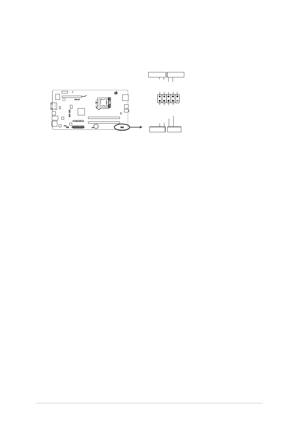
6. System panel connector (10-1 pin PANEL)
This connector supports several chassis-mounted functions.
P7H5510LT
P7H5510LT System panel connector
PIN 1
PWR BTN
PLED
+
PLED
-
PWR
GND
IDE_LED
+
IDE_LED
-
Groun
d
Rese
t
F_PANEL
PWR LED
HD_LED
RESET
- CG8565 (410 pages)
- CG8565 (246 pages)
- CS5111 (26 pages)
- CS5120 (1 page)
- ET1611PUK (38 pages)
- S2-P8H61E (80 pages)
- P2-PH1 (80 pages)
- P1-P5945G (80 pages)
- P2-P5945GCX (90 pages)
- CG8270 (218 pages)
- CG8270 (536 pages)
- CG8270 (72 pages)
- CG8270 (76 pages)
- CG8270 (534 pages)
- CG8270 (362 pages)
- P3-P5G31 (100 pages)
- P3-PH4 (80 pages)
- P2-M2A690G (80 pages)
- P2-M2A690G (8 pages)
- P4-P5N9300 (1 page)
- P4-P5N9300 (82 pages)
- P1-P5945GC (92 pages)
- P2-P5945GC (92 pages)
- P3-P5G33 (98 pages)
- T3-P5945GC (80 pages)
- T3-P5945GCX (80 pages)
- P2-M2A690G (94 pages)
- T3-PH1 (80 pages)
- T3-PH1 (82 pages)
- T5-P5G41E (82 pages)
- T5-P5G41E (76 pages)
- S1-AT5NM10E (68 pages)
- ES5000 (174 pages)
- T4-P5G43 (104 pages)
- T-P5G31 (92 pages)
- BT6130 (60 pages)
- BT6130 (54 pages)
- BT6130 (2 pages)
- CG8265 (210 pages)
- CG8265 (350 pages)
- CM1740 (330 pages)
- CM1740 (70 pages)
- CM1740 (198 pages)
- P6-M4A3000E (59 pages)