Universal Remote Control (URS) MRF-200 User Manual
Page 7
P
Paagge
e 4
4
M
MR
RF
F--2
20
00
0 B
B
A
AS
SE
E
S
S
T
TA
AT
TIIO
ON
N
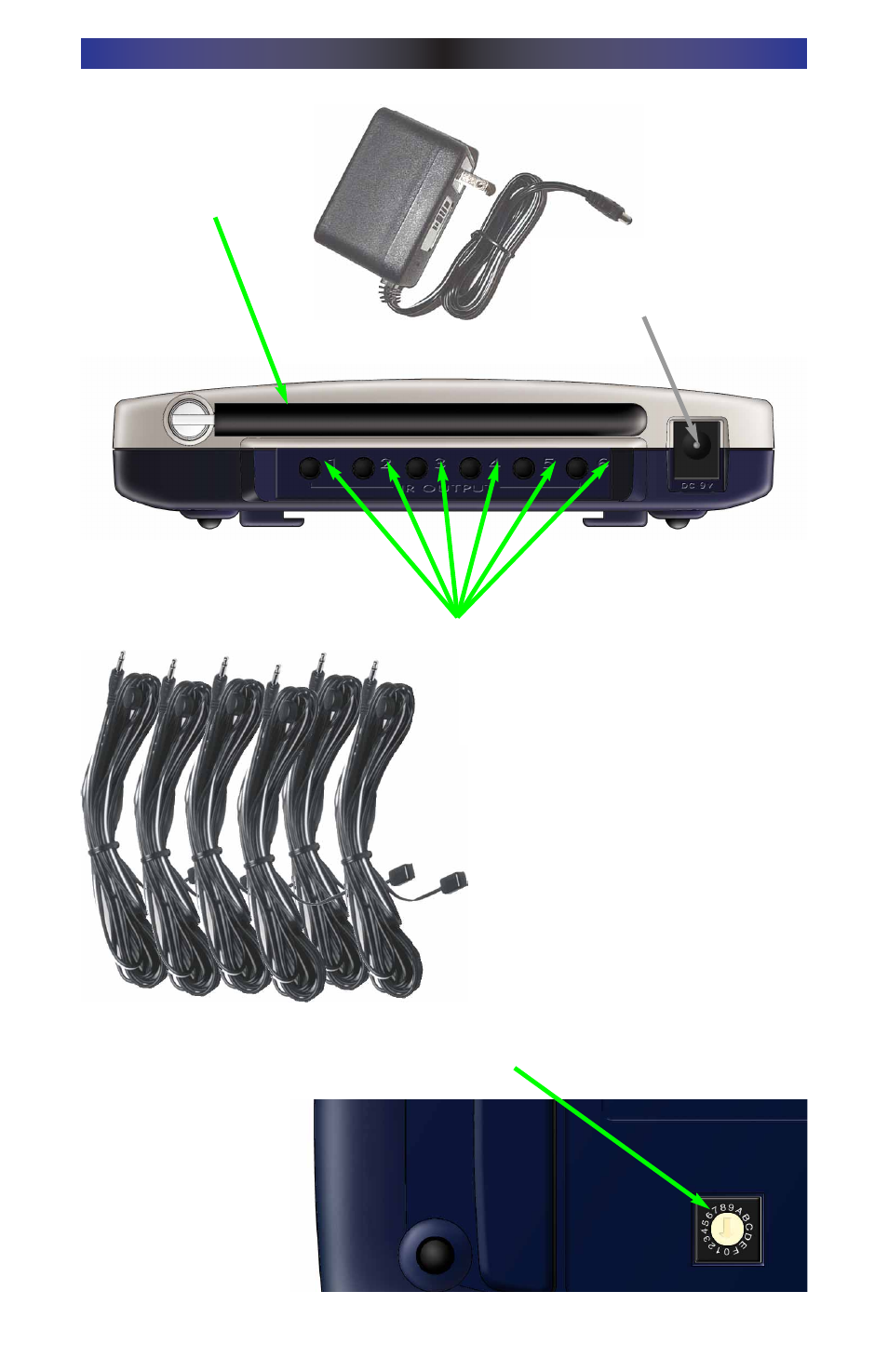
Six Plug-In Flashers are supplied
with 10 foot cables and six extra
self-adhesive pads (in case a flash-
er has to be repositioned).
Bottom panel Dial sets the Receiver ID# when
more than one MRF-200 receiver is used.
Included 9V power supply
plugs into the MRF-200’s
power connector.
Integrated Antenna
swings in any direction
to optimize RF recep-
tion and range.
Six Rear Flasher Line Output Jacks
connect flashers for control of A/V
components out of sight of the MRF-
200’s Front Blaster.
See also other documents in the category Universal Remote Control (URS) Remote control:
- URC Professional Line MX900 (16 pages)
- PHAZR -5 UR5U-9020L_ (2 pages)
- RF10 (36 pages)
- AVEX R6 (44 pages)
- RFX150 (16 pages)
- SL-7000 (45 pages)
- MX-3000 (12 pages)
- MX-3000 (19 pages)
- WR7 (52 pages)
- Unifier URC-100 (52 pages)
- MX-6000 (19 pages)
- Universl Remote (112 pages)
- UNIFIERTM URC-100 (56 pages)
- AMINO-4 (2 pages)
- URC-4041 (36 pages)
- UR3-SR (2 pages)
- RF30 (35 pages)
- KP-4000 (20 pages)
- UR4-EXP (2 pages)
- UR3-SR2 (20 pages)
- UR3-SR2 (25 pages)
- Home Theater Master SL-9000 (59 pages)
- TX-1000 (16 pages)
- TX-1000 (20 pages)
- Universal SL-8000 (52 pages)
- UR4-DSR (2 pages)
- RF20 (35 pages)
- MX-800 (16 pages)
- UR4U-MDVR2 (2 pages)
- MX-850 (9 pages)
- MX-850 (20 pages)
- MX-810 (20 pages)
- MX-880 (20 pages)
- MX-880 (22 pages)
- SL-9000 (59 pages)
- Easy Clicker OCE-0009D (13 pages)
- omega MX-650 (60 pages)
- UR4-DCT (2 pages)
- Remote control HCCUR (16 pages)
- Cablevision Remote Control UR2-CBL-CV04 (2 pages)
- MX-900 (44 pages)
- CLIKR-5 UR5U-8700L-IP (2 pages)
- R6 (41 pages)
- URC-300 (56 pages)