Installation, Continued grounding the media converter – Transition Networks SAPTF33xx-100 User Manual
Page 2
Installation
-- Continued
Grounding the Media Converter
The SAPTF33xx-1xx single-slot chassis comes equipped with grounding lugs
located on the back panel. They require a grounding conductor wire
terminated with a two-hole, compression-type, grounding connector. The
grounding wire -- which must be a copper conductor -- is not included with
the chassis and must be provided by the customer/installer.
The electrical conducting path from the single-slot chassis must:
•
Flow via the grounding lugs to the common bonding network (CBN).
•
Be of sufficiently low impedance to conduct fault currents likely to be
imposed on the media converter, and
•
Enable proper operation of any over-current protection devices.
The conductor must be fastened to the grounding lugs with the enclosed anti-
rotation star-washers and lug-nut fasteners. The applied torque required to the
connector lug-nut fasteners is specified by the connector’s manufacturer.
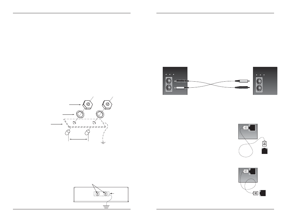
To properly ground the SAPTF33xx-1xx single-slot chassis:
1.
Obtain one (1) grounding conductor (12 AWG copper wire gauge or
larger) with a two-hole, compression-type, grounding connector.
2.
Attach the grounding conductor to the converter by placing the two-hole
connector onto the grounding lugs and fasten with the enclosed lock-
washers / lug-nuts at the proper torque (per the manufacturer’s
specification).
3.
Attach the opposite end of the
grounding conductor to the
common bonding network
(CBN).
grounding lugs
earth ground
grounding
connector
and wire
6
SAPTF33xx-1xx
24-hour Technical Support: 1-800-260-1312 -- International: 00-1-952-941-7600
3/4-inch
spacing
Grounding lugs
(6-32, 1/8" diam.)
12 AWG copper wire
(not included)
Star washer (included)
Lug nuts (included)
Two-hole, compression-type
grounding connector
(not included)
7
Click the “Transition Now” link for a live Web chat.
Installation
-- Continued
Installing the Cable -- Standard Configuration
NOTE: Unit B MUST be configured for Standard Configuration (see page 4).
Fiber
1.
Locate or build fiber cable with male, two-stranded TX to RX connectors
installed at both ends.
2.
Connect the fiber cables to Unit A (SAPTF33xx-100) as described:
•
Connect the male TX cable connector to the female TX port.
•
Connect the male RX cable connector to the female RX port.
3.
Connect the fiber cables to Unit B (SAPTF33xx-110) as described:
•
Connect the male TX cable connector to the female RX port.
•
Connect the male RX cable connector to the female TX port.
Copper
1.
Locate or build copper cables with male, RJ-
11C connectors installed at both ends.
2.
Connect the copper cables to Unit A
(SAPTF33xx-100) as described:
•
Connect the RJ-11C connector at one
end of the cable to the RJ-11C port on
Unit A.
•
Connect the RJ-11C connector at the
other end of the cable to the RJ-11C port
on the Central Office.
3.
Connect the copper cables to Unit B
(SAPTF33xx-110) as described:
•
Connect the RJ-11C connector at one
end of the cable to the RJ-11C port on
Unit B.
•
Connect the RJ-11C connector at the
other end of the cable to the RJ-11C port
on the telephone device.
TX
RX
ACT
SDF
PWR
TX
RX
ACT
SDF
PWR
Connect to the
RJ-11C port on the
Central Office.
Connect to the
RJ-11C port on the
telephone device.
Unit A
Unit B
Unit A
Unit B