3system level description, Sleu063 – Texas Instruments TVP5146EVM User Manual
Page 8
SLEU063
8
TVP5160EVM User’s Guide
3
System Level Description
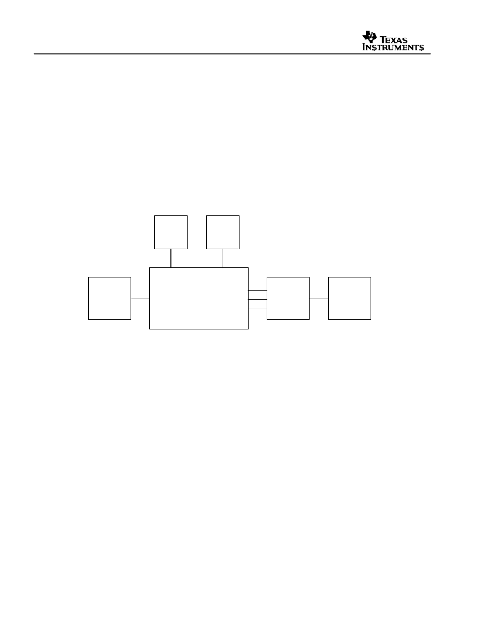
The system block diagram illustrated in Figure 2 provides an example of how the TVP5160EVM
may be used for evaluation. Typically, the analog input is a CVBS signal provided by a video
source such as a pattern generator or a DVD player running a test DVD.
The TVP5160EVM itself is configured with the provided 5-V supply and the parallel port cable.
The analog output is typically YPbPr to reduce the number of artifacts caused by backend
processing or re-encoding. These outputs are then fed into a high-end or studio-quality display
monitor such as a Sony Trinitron.
At the same time, the CVBS output from the encoder may also be fed into a video test
measurement system such as the Tektronix VM700. This allows various tests to be run and
also allows the user to analyze the video waveform or vectorscope.
Figure 2.
TVP5160EVM System Level Block Diagram
Tektronix
TG2000
Video
Source
TVP5160EVM
CVBS
5V
Supply
NTSC/PAL
Monitor
Tektronix
VM700
Video
Measurement
Pb
CVBS
Y
Pr
PC
Tektronix
TG2000
Video
Source
TVP5160EVM
CVBS
5V
Supply
NTSC/PAL
Monitor
Tektronix
VM700
Video
Measurement
Pb
CVBS
Y
Pr
PC