2board level description, Sleu063, 1 analog inputs – Texas Instruments TVP5146EVM User Manual
Page 4
SLEU063
4
TVP5160EVM User’s Guide
2
Board Level Description
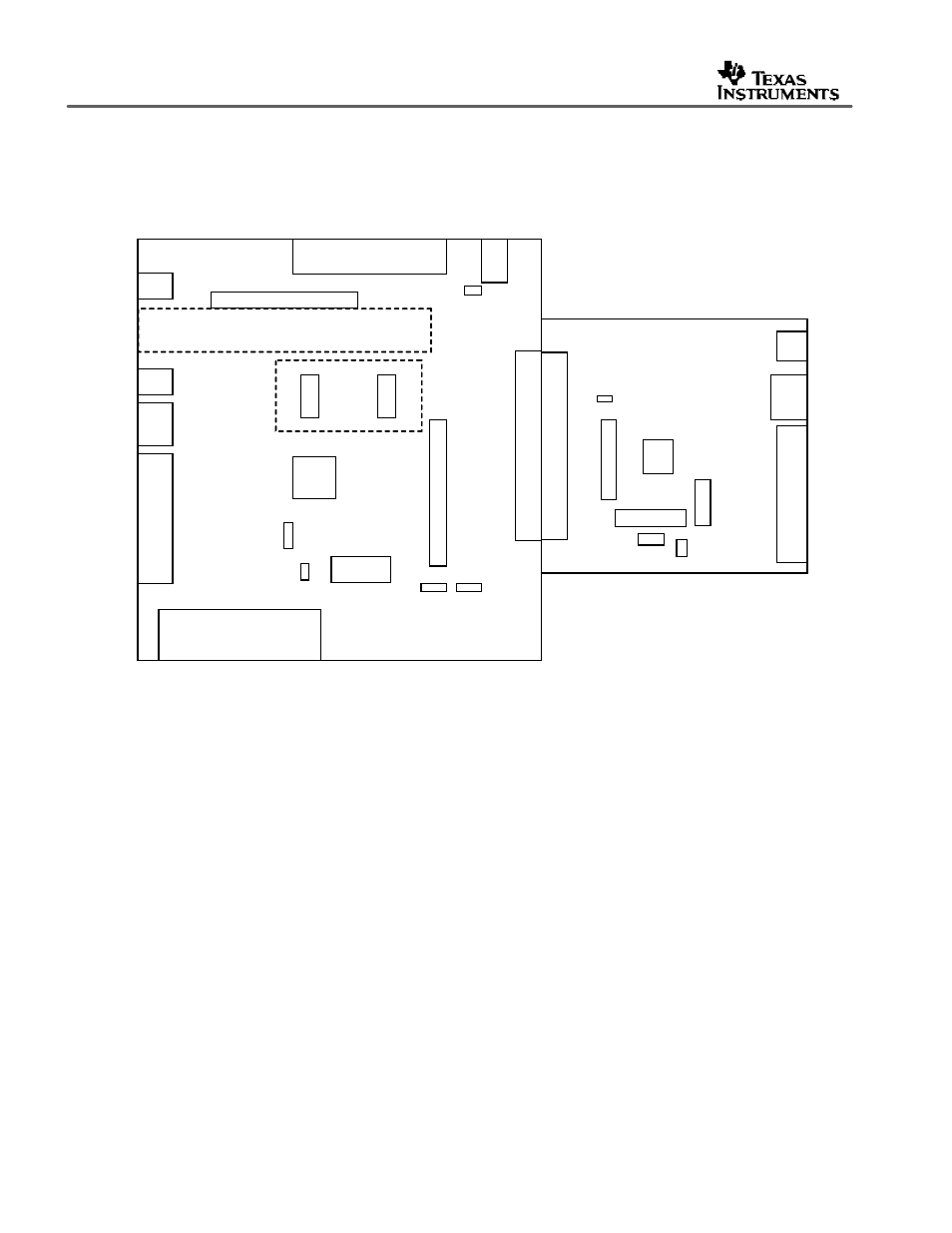
Figure 1 illustrates the various features available on the TVP5160EVM.
Figure 1.
TVP5160EVM Block Diagram
2.1
Analog Inputs
The TVP5160EVM makes use of all the available inputs on the TVP5160 decoder. The
following inputs are available for use:
?
Composite (CVBS)
?
S-Video
?
YPbPr (SD/ED)
?
SCART (CVBS and component RGB)
?
Tuner interface (CVBS)
?
VBI decoder interface (analog/digital RGB)
NOTE: The S-Video (Y/C) input is shared with the SCART (CVBS and R) inputs and must not be
connected simultaneously.
Table 1 shows the pins used for the inputs described above.
ADV7311
120
-pin Header Connector
Power
Good
LED
Composite
Testpoints
I2C
Address
Select
S-Video
YPbPr
(SD/ED)
Reset
Composite
S-Video
YPbPr
(SD/ED)
SCART
SDRAM
120
-pin Header Connector
5V
Power
Power
Good
LED
DB25 (I2C)
Tuner Interface
VBI
Decoder
Interface
TVP5160
FSS
Select
I2C
Address
Select
Testpoints
Power
Down
Reset
Analog Output
Composite
S-Video
YPbPr
(SD/ED)
SCART
SDRAM
120
-pin Header Connector
5V
Power
Power
Good
LED
DB25 (I2C)
Tuner Interface
VBI
Decoder
Interface
TVP5160
FSS
Select
I2C
Address
Select
Testpoints
Power
Down
Reset
Analog Output