3a connector pin assignments – Toshiba CMOS Color Camera IK-HR1D User Manual
Page 9
9
DVI-I terminal
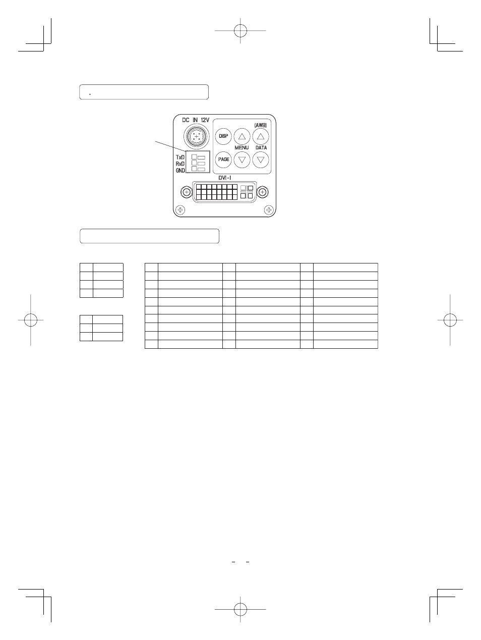
4. 3A Connector Pin Assignments
DC IN 12V terminal
1
+12V
2
+12V
3
GND
4
GND
REMOTE terminal
1
2
3
TXD
RXD
GND
1
2
3
4
5
6
7
NC
8
Analog Vertical Sync
NC
NC
NC
Data2-
Data2+
Data2 Shield (GND)
9
10
11
12
13
14
15
GND
16
Hot Plug Detect
NC
NC
+5V
Data1-
Data1+
Data1 Shield (GND)
17
18
19
20
21
22
23
Clock+
24
Clock-
C
1
Analog Red
C
4
Analog Horizontal Sync
C
2
Analog Green
C
5
Analog GND
C
3
Analog Blue
NC
NC
Clock Shield (GND)
Data0-
Data0+
Data0 Shield (GND)
Rear panel view
4
3 Connection on Rear Panel
㪩㪜㪤㪦㪫㪜
C1
1
9
17
2
10
18
3
11
19
4
12
20
5
13
21
6
14
22
7
15
23
8
16
24
C2
C3
C4
C5
1
1
2
3
4
2
3
* For connecting to the REMOTE terminal, use a shielded cable. Connect a cable correctly,
or it may be damaged.
See also other documents in the category Toshiba Cameras:
- PDR-3310 (2 pages)
- V Series (2 pages)
- CSGS15BC23 (56 pages)
- HIGH RESOLUTION CMOS CAMERA CSB1100F (2 pages)
- IK-VR01A (19 pages)
- T10 (59 pages)
- IK-DP01A (2 pages)
- IK-TF2 (32 pages)
- PDR-T20 (70 pages)
- PDR-M60 (64 pages)
- IK-53N (22 pages)
- IK-1000 (2 pages)
- TELI CS3950DIF (24 pages)
- PDR-M81 (142 pages)
- IK-644A (9 pages)
- pmn (60 pages)
- PDR-M700 (2 pages)
- IK-DP30A (2 pages)
- IK-WB11 (8 pages)
- TELI CS5260BDP (5 pages)
- TLP848 (12 pages)
- IK-65WDA (32 pages)
- IK-6550A (2 pages)
- PDR-M11 (272 pages)
- IK-52V (2 pages)
- PDR-M70 (2 pages)
- USB Webcam (17 pages)
- CSB1100CL-10 (16 pages)
- IK-6410A (16 pages)
- IK-TF7C (36 pages)
- PDR-M71 (140 pages)
- IK-629A (9 pages)
- IK-WB15AIP (2 pages)
- IK-WR01A (16 pages)
- IK-DF01A (16 pages)
- IK-6210A (2 pages)
- PDR-M65 (109 pages)
- CCD IK-6400A (4 pages)
- IK-TF9C (32 pages)
- CS6940CL (17 pages)
- IK-TF5 (36 pages)
- CCD Monochrome Camera IK-539A (10 pages)
- PDR-M5 (120 pages)
- CS3950D (23 pages)