Troubleshooting the transceiver, Cable specifications – Transition Networks FAST ETHERNET E-TX-MC01 User Manual
Page 2
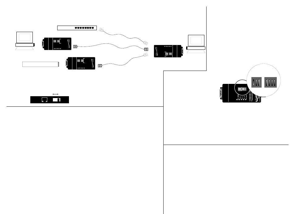
10BASE-T or 100BASE-TX Hub
OR
OR
Hub with MII connector
RX
100BASE-TX
TRANSCEIVER
E-TX-MC01
Collision
TX
Link
Power
1
2
3
4
5
Ad
dr
es
s
(1
-5
)
ON
OF
F
MDI-X switch setting
MDI-X switch setting
RX
100BASE-TX
TRANSCEIVER
E-TX-MC01
Collision
TX
Link
Power
1 2 3
4
5
A d d r e s s ( 1 - 5 )
O N
O F F
RX
100BASE-TX
TRANSCEIVER
E-TX-MC01
Collision
TX
Link
Power
1 2 3
4
5
A d d r e s s ( 1 - 5 )
O N
O F F
MDI switch setting
1. Is the power LED on the transceiver illuminated?
NO
•
Verify that the transceiver is installed properly in the MII port and that the device is
powered ON?
•
Contact Technical Support at (800) 260-1312 or at (800) LAN-WANS.
YES
•
Proceed to step 2.
2. Is the Link LED illuminated?
NO
•
Check the copper cables for proper connection. (If possible, try a different cable.)
•
Try setting a non-zero physical address.
•
Contact Technical Support at (800) 260-1312 or at (800) LAN-WANS.
YES
•
Proceed to step 3.
3. Is the copper cable connected properly?
NO
•
Verify that straight-through copper cable is installed and that MDI-MDI-X switch is set
correctly.
•
Contact Technical Support at (800) 260-1312 or at (800) LAN-WANS.
YES
C
T h i l S
(800) 260 1312
(800) LAN WANS
Troubleshooting the Transceiver
If the E-TX-MC01 transceiver fails, determine the answers to the following questions:
Installation Notes
Straight Through/Crossover Cable Requirements and Pin Specifications
NOTE: Straight-through/crossover requirements are satisfied using the MDI/MDI-X switch with
straight-through cable. Cable connections between a hub and the media converter require the
MDI/MDI-X switch to be set to MDI. Cable connections between the media converter and a
terminal, transceiver or NIC require the switch to be set to MDI-X
Using small flatblade screwdriver or similar tool
and referring to label at front of media converter,
set MDI/MDI-X switch position for site installation.
MDI
position
MDI-X
position
•
Be certain that 10BASE-T/100BASE-TX
MDI/MDI-X switch is set correctly for site
installation. .
•
Set Switches according to site installation:
Switches 1-5: The transceiver is shipped with
rocker switch 1 set to the default ON=UP
and with switches 2-5 set to the default
OFF=DOWN, setting the transceiver physical
address to a value of “1”.
In all known cases, the default rocker switch 1-5
setting is the correct physical
address for network installations.
ONLY IF THIS ADDRESS
SHOULD FAIL, refer to the chart
on the back page for direction for
setting the binary transceiver
physical address to a site-specific value from 1 to 31.
Switch 6-7: The transceiver is shipped with rocker switches 6 and 7 set to
the default OFF=DOWN, which sets the data-transfer mode to “auto-
negotiation”..
•
Set switch 6 to ON=UP when the transceiver is connected to a
100BASE-TX half-duplex device.
•
Set switch 7 to ON=UP when the transceiver is connected to a
10BASE-T half-duplex device.
CABLE SPECIFICATIONS
The physical characteristics of the media cable must meet or exceed IEEE
802.3u 100BASE-TX specifications.
100BASE-TX CABLE SPECIFICATIONS
Category 5 wire or better is required. Either shielded twisted pair
(STP) or unshielded twisted pair (UTP) can be used. Use a straight-
through cable configuration (see back page).
Category 5:
Gauge
24 to 22 AWG
Attenuation
20 dB/1000’ @ 10 MHz
Impedance 100
Ω
±10% @ 10 MHz
Maximum Cable Distance:
100 meters (330 feet)Maximum
Config. Switches
1 2 3
4 5 6 7
PL/FDX
MDI MDI-X
100BASE-FX
TRANSCEIVER
E-FX-MC01
1 2 3
4
5
A d d r e s s ( 1 - 5 )
O F F
O F F
6 7