Step 4 – add end-devices, Step 6 – next steps and more information – Texas Instruments CC2530ZNP User Manual
Page 2
SWRU268A
October 2010
2/2
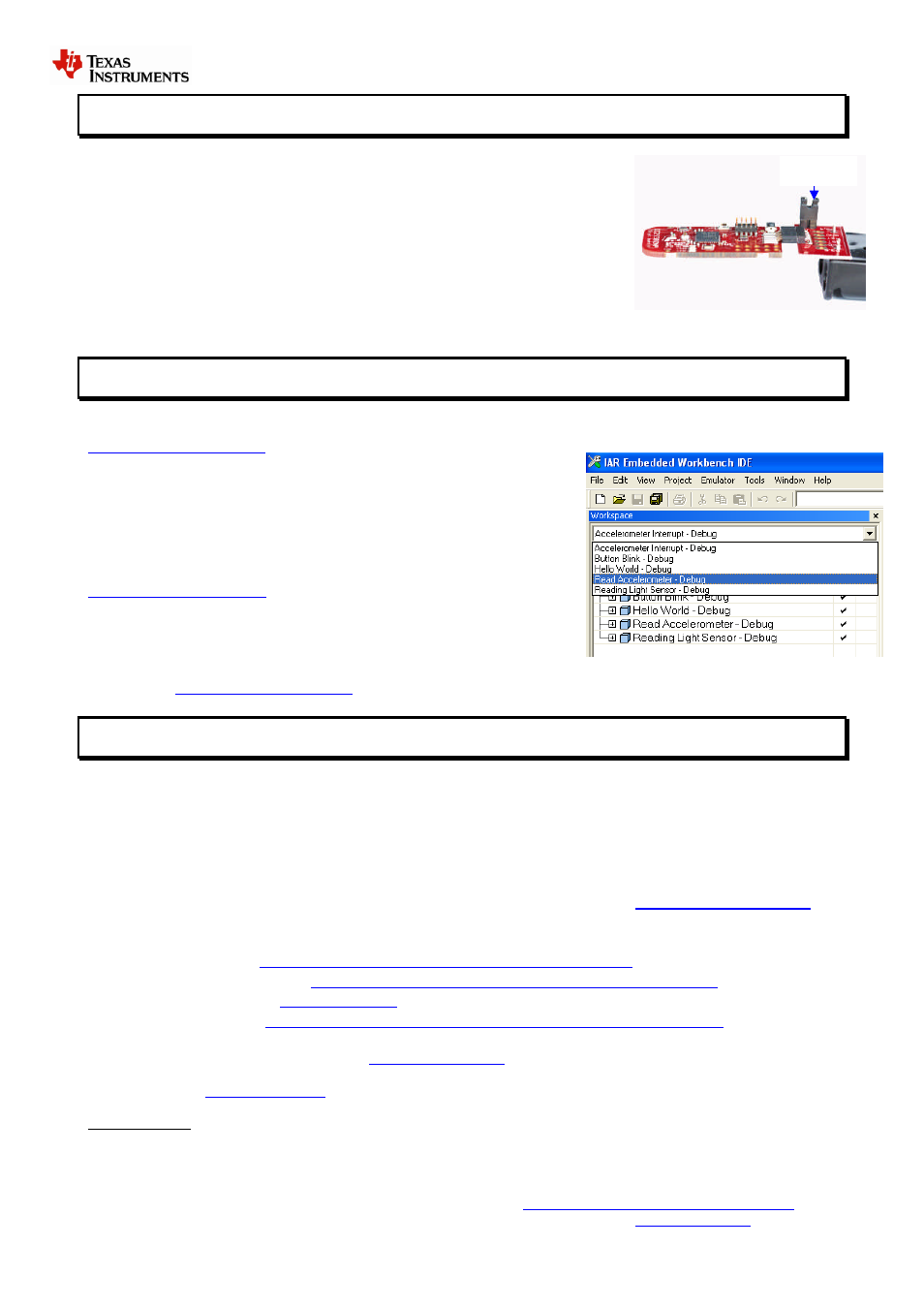
Jumper
STEP 4 – Add end-devices
Insert batteries in one or more of the battery boards and make sure the jumper is
connected to power the end-device.
When the end-device sends information to the coordinator, an RX-message will
appear in the terminal. The green LED on the end-devices will blink when they are
sending a message. If the end device loses connection to the coordinator the green
LED will be on constantly.
The message includes network information as well as battery voltage and light sensor
readings. The messages are sent every 4 seconds periodically when the board is not
moving. If the board is moving the messages are sent when the accelerometer
generates an interrupt.
STEP 5 –Using IAR Embedded Workbench for programming/debugging
To test the software examples, use IAR Embedded Workbench for MSP430. A free “kickstart” edition with 4 Kbyte (16
Kbyte for MSP430F2274 when using the --ks_version linker option) code size limitation is available from
Download the compiler and install the IAR
Embedded Workbench. Most of the example codes included with the
CC2530ZNP-Mini kit are below 4 Kbyte.
Open one of the four the workspace file (xx.eww) in IAR. It is recommended to
start with the Hardware Interface Examples. The workspace files are located
at
C:\Texas Instruments\CC2530ZNP Mini Kit\ZNP Examples\IAR
.
For detailed information about the sample applications, please check the
CC2530ZNP wiki page:
Plug the USB stick with a target board into the USB port and press “Download
and Debug” from the “Project” menu.
If you need more information how to use the IAR Embedded Workbench for compiling and debugging please see the
user’s guide:
STEP 6 – Next steps and more Information
Extensive examples are provided to help you get started. Building and running each example is recommended to
become acquainted with the device. Start with the Hardware Interface Examples, then the ZNP Interface Examples, and
finally the Communications Examples. Refer to the examples’ wiki page for more information.
Use ZNP target board connected to the USB stick to test these examples and keep a UART terminal window open to see
the data sent to the PC. The board connected to the USB cable should normally be selected as Coordinator while the
battery boards are End-Devices. The development kits are shipped with the “Simple Applications” coordinator and
end-devices programmed. Hex files for the MSP430 sample applications and for CC2530ZNP can be found at:
C:\Texas Instruments\CC2530ZNP Mini kit\Bin
. These files can be programmed with the
For detailed information about the sample applications please see the following resources:
CC2530ZNP wiki page:
CC2530ZNP product web page:
CC2530 product web page
ZigBee training material:
The Low Power RF Online Community has forums, blogs and videos. Use the forums to find information, discuss
and get help with your design. Join us at
If you want to modify the CC2530ZNP image to fit your application the source code can be found on the Z-stack
product page:
Important note: The CC2530ZNP Mini kit is an educational tool that allows developers to get get familiar with basic
ZigBee networks. It is not intended as a ZigBee reference design. It is based on a 32Kbyte flash MSP430, because of
this it does not support official ZigBee profiles that are required to make ZigBee certified products.
Do you need more than 32Kbyte of flash? The full ZigBee development kit allows development of public ZigBee profiles.
Try the ZigBee Application Processor with support for ZigBee profiles:
.
Texas Instruments has ZigBee solution for any application; see the complete offering on