As311 overview – Toshiba AS311 User Manual
Page 15
User’s
Manual
13
1. AS311 Overview
Hardware reset switch
When this switch is pressed, the AS311 will be reset. Use this switch when you
have changed the switch settings.
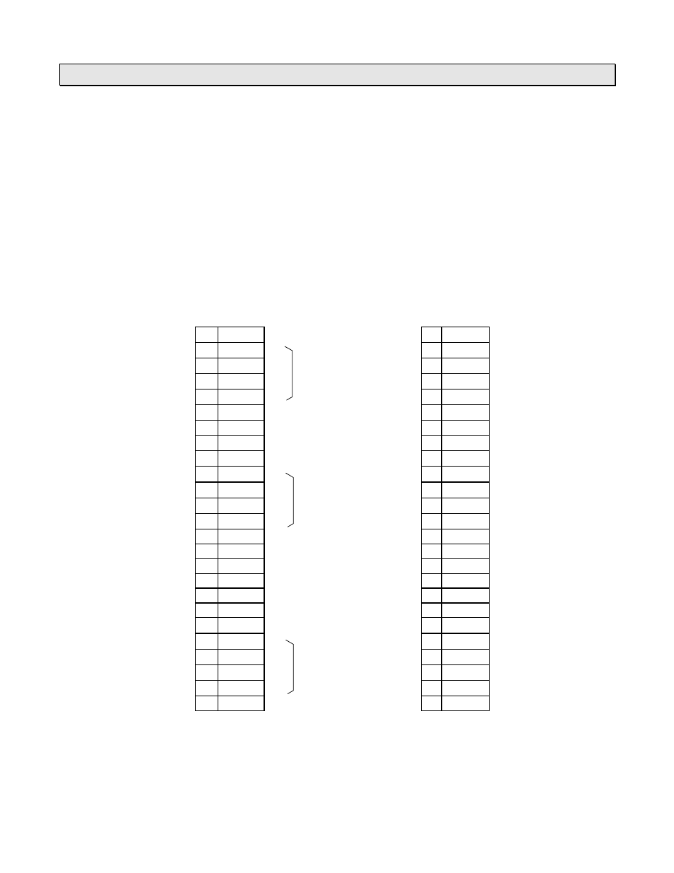
Channel 1 and channel 2 serial ports
Used to connect the serial transmission line (RS-232C or RS-422). D-Sub 25-pin
female connectors are provided on the AS311.
The pin assignment is as follows.
Channel 1
Channel 2
(RS-232C/RS-422)
(RS-232C)
1 FG
↔
1 FG
↔
2 TXD
→
2 TXD
→
3 RXD
←
for RS-232C
3 RXD
←
4 RTS
→
4 RTS
→
5 CTS
←
5 CTS
←
6
6 DSR
←
7 SG
↔
7 SG
↔
8
8
9 5 Vdc
→
9 5 Vdc
→
10
TXDA
→
10
11
RXDA
←
for RS-422
11
12
RTSA
→
12
13
CTSA
←
13
14
14
15
15
16
16
17
17
18
18
19
19
20
DTR
→
for RS232C
20 DTR
→
21
TXDB
→
21
22
RXDB
←
for RS-422
22
23
RTSB
→
23
24
CTSB
←
24
25
25
•
The arrow on the above figure shows the signal direction.
•
FG is connected with the T3’s frame ground internally. (both channels)
•
DTR and RTS are ON while power is on.
•
Data transmitting is available when CTS is ON. DSR has no effect for transmission.
•
Pin 9 (5 Vdc) can be used to supply 5 Vdc power. (total max. 50 mA)