Half-duplex network, Fault isolation and correction, Bit rule – Transition Networks SSETF10XX-200 User Manual
Page 4
[email protected] -- Select the “Transition Now” Link for a Live Web Chat
7
HALF-DUPLEX NETWORK
512-Bit Rule
In a half-duplex network, the maximum cable lengths are determined by the
round trip delay limitations of each Fast Ethernet™ collision domain. (A
collision domain is the longest path between any two terminal devices, e.g. a
terminal, switch, or router.)
The 512-Bit Rule determines the maximum length of cable permitted by
calculating the round-trip delay in bit-times (BT) of a particular collision
domain. If the result is less than or equal to 512 BT, the path is good.
To calculate the round-trip delay for a collision domain:
1.
Find the collision domain, i.e. the longest
path between any two terminal devices
(e.g., terminal, switch, and/or router).
2.
Calculate the round-trip delay in bit-times
for each length of cable.
4.
Determine the bit-time values for each
device (see table to the right).
3.
Add the bit-time values for each length of
cable and the bit-times for each device.
NOTE: The 512-Bit Rule applies separately to each collision domain.
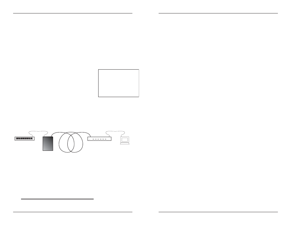
The example below illustrates a collision domain bound by a router on one
end and a terminal on the other.
Since the total of the bit-times in this example is less than 512 (see chart
below), the path is good.
Terminal
= 50 BT
10 meters TP
= 11.1BT
150 meters fiber = 150BT
Class I Hub = 140BT
Switch = 50BT
Media Converter
= 12BT
10 meters TP
= 11.1BT
Sum of the bit-times for the example collision domain:
Router
=
50.0 BT
10 m TP cable
(10m x 1.11 BT/m)
= 11.1 BT
SSETF101xx-200
=
12.0 BT
150 m fiber cable
(150 m x 1.0 BT/m)
= 150.0 BT
Class I hub
= 140.0 BT
10 m TP cable
(10m x 1.11 BT/m)
= 11.1 BT
Terminal
=
50.0 BT
Total
= 424.2 BT
Class I hub
140 BT
Class II hub
92 BT
terminal/router
50 BT
1 meter TP cable
1.11 BT
1 meter fiber cable 1 BT
Fast Ethernet switch 50 BT
SSETF10xx-200
12 BT
8
SSETF10xx-200
Tech Support: 800-260-1312 International: 952-941-7600 7am-6pm CST (GMT-6:00)
FAULT ISOLATION and CORRECTION
If the Media Converter fails, isolate and correct the fault by determining the
answers to the following questions and then taking the indicated action:
1.
Is the P(o)W(e)R LED on the Media Converter illuminated?
NO
•
Is the power adapter the proper type of voltage and cycle frequency
for AC outlet?
•
Is the power adapter properly installed in the Media Converter and in
the outlet?
•
Does the grounded AC outlet provide power?
•
Contact Technical Support: US/Canada: 1-800-260-1312,
International: 00-1-952-941-7600.
YES
•
Proceed to step 2.
2.
Is the LKC LED illuminated?
NO
•
Check the twisted pair cables for proper connection.
•
Contact Technical Support: US/Canada: 1-800-260-1312,
International: 00-1-952-941-7600.
YES
•
Proceed to step 3.
3.
Is the LKF LED illuminated?
NO
•
Check the fiber cables for proper connection.
•
Verify that the TX and RX cables on the Media Converter are
connected to the RX and TX ports, respectively, on the other device.
•
Contact Technical Support: US/Canada: 1-800-260-1312,
International: 00-1-952-941-7600.
YES
•
Proceed to step 4.
4.
Is the 100 LED illuminated?
NO
•
The Media Converter has selected 10 Mb/s operation. If this is not the
correct speed, disconnect and reconnect the 10/100Base-TX cable to
restart the initialization process.
•
Proceed to step 5.
YES - SLOWLY FLASHING
•
The Media Converter is selecting between 10 Mb/s and 100 Mb/s
speed or one or both of the links is down. If persistent, disconnect
and reconnect either cable to restart the initialization process.
•
Proceed to step 5.
YES
•
The Media Converter has selected 100 Mb/s operation. If this is not
the correct speed, disconnect and reconnect the 10/100Base-TX
cable to restart the initialization process.
•
Proceed to step 5.