Data sheet: supereta, Iqm series –single output quarter brick, Electrical data – TDK Supereta iQM Series User Manual
Page 5
Data Sheet: Supereta
TM
iQM Series –Single Output Quarter Brick
©2004-2006 TDK Innoveta Inc.
iQM 12V/17A Datasheet 8/4/2006
℡
(877) 498-0099
5/15
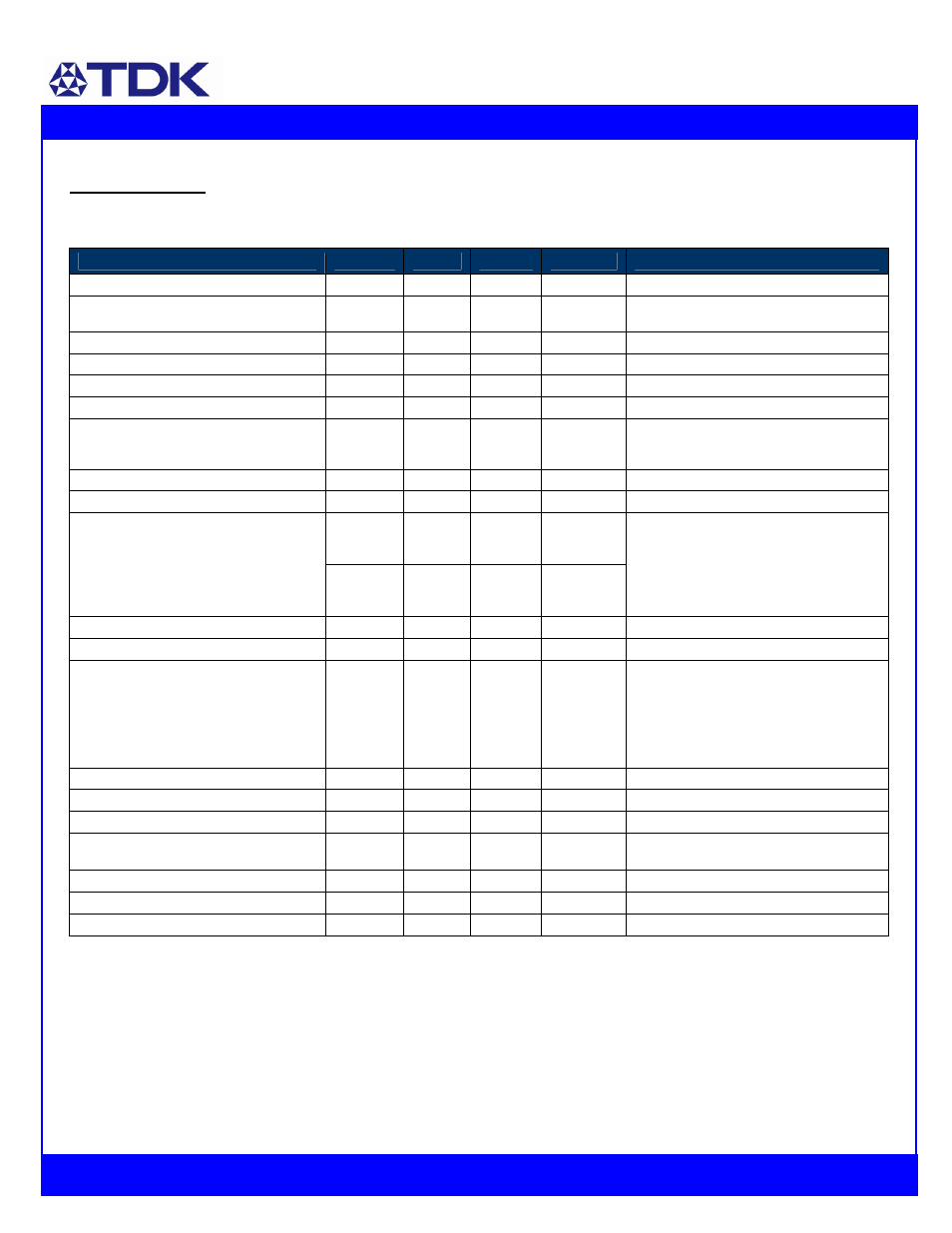
Electrical Data:
iQM48017A120V-000 through -009: 12V, 17A Output
Characteristic
Min
Typ
Max
Unit
Notes & Conditions
Output Voltage Initial Setpoint
11.7
12
12.3
Vdc
Vin=Vin,nom; Io=Io,max; Tc = 25˚C
Output Voltage Tolerance
11.6
12
12.4
Vdc
Over all rated input voltage, load, and
temperature conditions to end of life
Efficiency
---
90.5
---
%
Vin=Vin,nom; Io=Io,max; Tc = 25˚C
Line Regulation
---
3
24*
mV
Vin=Vin,min to Vin,max, Io and Tc fixed
Load Regulation
---
3
24*
mV
Io=Io,min to Io,max, Vin and Tc fixed
Temperature Regulation
---
25
100*
mV
Tc=Tc,min to Tc,max, Vin and Io fixed
Output Current
3
---
17
A
At loads less than Io,min the module will
continue to regulate the output voltage, but
the output ripple may increase slightly
Output Current Limiting Threshold
---
18.8
---
A
Vo = 0.9*Vo,nom, Tc Short Circuit Current --- 0.1 --- A Vo = 0.25V, Tc = 25 --- 60 120 mVpp Output Ripple and Noise Voltage --- 15 --- mVrms Vin=48V, Io ≥Io,min, Tc=25˚C. Measured across one 0.1uF, one 1.0 uF, one 47uF Output Voltage Adjustment Range 80 --- 110 %Vo,nom Note: Trim down to 60% is possible Output Voltage Sense Range --- --- 10 %Vo,nom Dynamic Response: --- --- 800 300 --- --- µS mV di/dt = 0.1A/uS, Vin=Vin,nom; load step Output Voltage Overshoot during startup 0 0 --- mV Vin=Vin,nom; Io=Io,max,Tc=25˚C Switching Frequency --- 155 --- kHz Fixed Output Over Voltage Protection 13.8 14.5 15.2 V External Load Capacitance 470 --- 4,400 † uF Minimum ESR > 2.5 m Ω. Tc=25˚C Isolation Capacitance --- 1000 --- pF Isolation Resistance 10 --- --- MΩ Vref 1.225 V Required for trim calculation † Contact TDK Innoveta for applications that require additional capacitance or using capacitors with very low ESR
ceramic, and a 470uF low esr aluminum
electrolytic capacitors located 2 inches
away – see input/output ripple
measurement figure; BW = 20MHz
Recovery Time to 10% of Peak Deviation
Transient Voltage
from 50% to 75% of Io,max, Tc=25˚C with at
least one 1.0 uF, one 47uF ceramic, and a
470uF low esr aluminum electrolytic
capacitors across the output terminals
* Engineering Estimate