TDK Supereta iQM Series User Manual
Page 12
Data Sheet: Supereta
TM
iQM Series –Single Output Quarter Brick
©2004-2006 TDK Innoveta Inc.
iQM 12V/17A Datasheet 8/4/2006
℡
(877) 498-0099
12/15
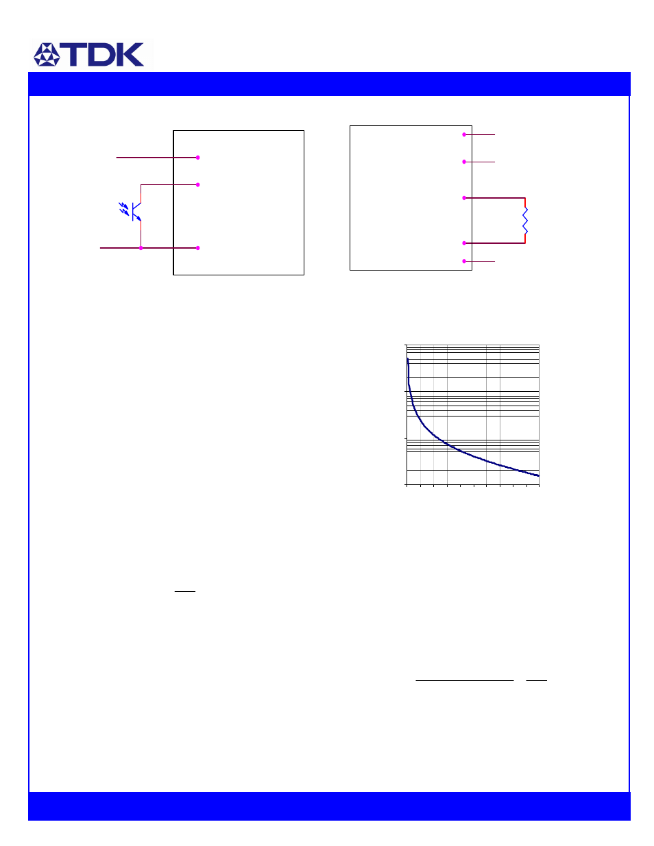
Vin(-)
On/ Off
Vin (+)
On/Off Circuit for positive or negative logic
Output Voltage Adjustment: The output
voltage of the module may be adjusted by
using an external resistor connected
between the trim pin 6 and either the Sense
(+) or Sense (-) pin. If the voltage trim
feature is not used, pin 6 should be left
open. Care should be taken to avoid
injecting noise into the module’s trim pin. A
small 0.01uF capacitor between the power
module’s trim pin and Sense (-) pin may
help to avoid this.
With a resistor between the trim pin and
Sense (-) pin, the output voltage is adjusted
down. To adjust the output voltage down a
percentage of Vout (
∆%) from Vo,nom, the
trim resistor should be chosen according to
the following equation:
)
2
%
100
(
11
.
5
−
∆
×
=
down
R
(k
Ω)
Where
∆%=100×(Vo,nom - Vdesired) / Vo_nom
The current limit set point does not increase
as the module is trimmed down, so the
available output power is reduced.
Sense(+)
Vout(+)
Vout(-)
Rdown
Trim
Sense(-)
Circuit to decrease output voltage
10
100
1000
10000
0 2 4 6 8 10 12 14 16 18 20
% Decrease in Output Voltage,
∆
(%)
Trim R
esistance (k
Ω
)
With a resistor between the trim pin and
sense (+) pin, the output voltage is adjusted
up. To adjust the output voltage up a
percentage of Vout (
∆%) from Vo,nom the
trim resistor (in k
Ω) should be chosen
according to the following equation:
)
2
%
100
%
%)
100
(
(
11
.
5
,
0
−
∆
−
∆
Ч
∆
+
Ч
Ч
=
Vref
V
R
nom
up