4 headphone connector (j900), 5 line output select (j50), 6 headphone select (j32) – Texas Instruments TAS5121 User Manual
Page 17
Headphone Connector (J900)
2-5
System Interfaces
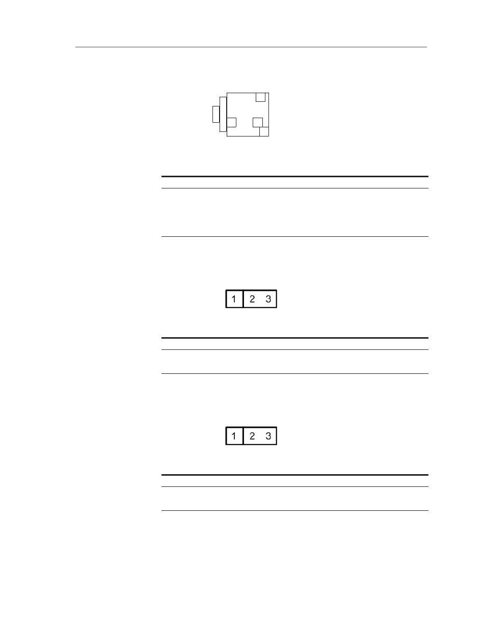
2.4 Headphone Connector (J900)
Figure 2−7. J900 Pin Numbers
(PCB connector top view)
2
3
4
1
Table 2−8. J900 Pin Description
Pin No.
Net-Name at Schematics
Description
1
OUT−L
Left headphone output
2
GND
Ground
3
—
For future use
4
OUT−R
Right headphone output
2.5 Line Output Select (J50)
Figure 2−8. J50 Pin Numbers
Table 2−9. J50 Pin Description
Pin No.
Description
1−2
Line outputs enabled
2−3
Line outputs disabled
2.6 Headphone Select (J32)
Figure 2−9. J32 Pin Numbers
Table 2−10.J32 Pin Description
Pin No.
Description
1−2
Headphone enabled
2−3
Headphone disabled
This manual is related to the following products: