Dimensions/weights/clearances, Installation – Trane RT-SVX19A-E4 User Manual
Page 8
Installation
RT-SVX19A-E4
8
Dimensions/Weights/Clearances
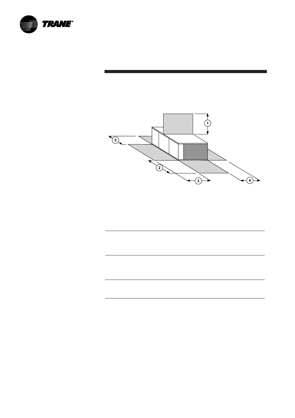
Figure 3 - Minimum clearances
Table 2 - Minimum clearances (mm)
The structure accommodating the unit(s) must be designed to support the
equipment in operation, as a minimum. Refer to Table 3a and the space
requirement plan.
Minimum clearance
UNIT
1
2
3
4
5
YKD/YKH 155
1900
1800
1220
1000
1300
YKD/YKH 175
1900
1800
1220
1000
1300
YKD/YKH 200
1900
1800
1220
1000
1300
YKD/YKH 250
1900
1800
1220
1000
1300
TKD/TKH 155
1900
1800
1220
1000
1300
TKD/TKH 175
1900
1800
1220
1000
1300
TKD/TKH 200
1900
1800
1220
1000
1300
TKD/TKH 250
1900
1800
1220
1000
1300
WKD/WKH 125
1900
1800
1220
1000
1300
WKD/WKH 155
1900
1800
1220
1000
1300
WKD/WKH 200
1900
1800
1220
1000
1300