Recommended operating conditions – Texas Instruments TPA3003D2 User Manual
Page 5
TPA3003D2
SLOS406A − FEBRUARY 2003 − REVISED MARCH 2003
5
www.ti.com
absolute maximum ratings over operating free-air temperature range (unless otherwise noted)
†
Supply voltage range: AV
CC,
PV
CC
−0.3 V to 15 V
. . . . . . . . . . . . . . . . . . . . . . . . . . . . . . . . . . . . . . . . . . . . . . . . . . . . .
Input voltage range, V
I
: MUTE, VREF, VOLUME, FADE
0 V to 5.5 V
. . . . . . . . . . . . . . . . . . . . . . . . . . . . . . . . . . . . . . . .
SD
−0.3 V to V
CC
+ 0.3 V
. . . . . . . . . . . . . . . . . . . . . . . . . . . . . . . . . . . . . . . . . . . . . . . . . . . . . . . .
RINN, RINP, LINN, LINP
−0.3 V to 7 V
. . . . . . . . . . . . . . . . . . . . . . . . . . . . . . . . . . . . . . . . . . . .
Supply current,
AV
DD
10 mA
. . . . . . . . . . . . . . . . . . . . . . . . . . . . . . . . . . . . . . . . . . . . . . . . . . . . . . . . . . . . . . . . . .
AVDDREF
10 mA
. . . . . . . . . . . . . . . . . . . . . . . . . . . . . . . . . . . . . . . . . . . . . . . . . . . . . . . . . . . . . .
Continuous total power dissipation
See Dissipation Rating Table
. . . . . . . . . . . . . . . . . . . . . . . . . . . . . . . . . . . . . . . . . .
Operating free-air temperature range, T
A
−40
°
C to 85
°
C
. . . . . . . . . . . . . . . . . . . . . . . . . . . . . . . . . . . . . . . . . . . . . . . . . .
Operating junction temperature range, T
J
−40
°
C to 150
°
C
. . . . . . . . . . . . . . . . . . . . . . . . . . . . . . . . . . . . . . . . . . . . . . . .
Storage temperature range, T
stg
−65
°
C to 150
°
C
. . . . . . . . . . . . . . . . . . . . . . . . . . . . . . . . . . . . . . . . . . . . . . . . . . . . . . . .
Lead temperature 1,6 mm (1/16 inch) from case for 10 seconds
260
°
C
. . . . . . . . . . . . . . . . . . . . . . . . . . . . . . . . . . . . .
† Stresses beyond those listed under “absolute maximum ratings” may cause permanent damage to the device. These are stress ratings only, and
functional operation of the device at these or any other conditions beyond those indicated under “recommended operating conditions” is not
implied. Exposure to absolute-maximum-rated conditions for extended periods may affect device reliability.
DISSIPATION RATING TABLE
PACKAGE
TA
≤
25
°
C
DERATING FACTOR
TA = 70
°
C
TA = 85
°
C
PFB
2.8 W
22.2 mW/
°
C
1.8 W
1.4 W
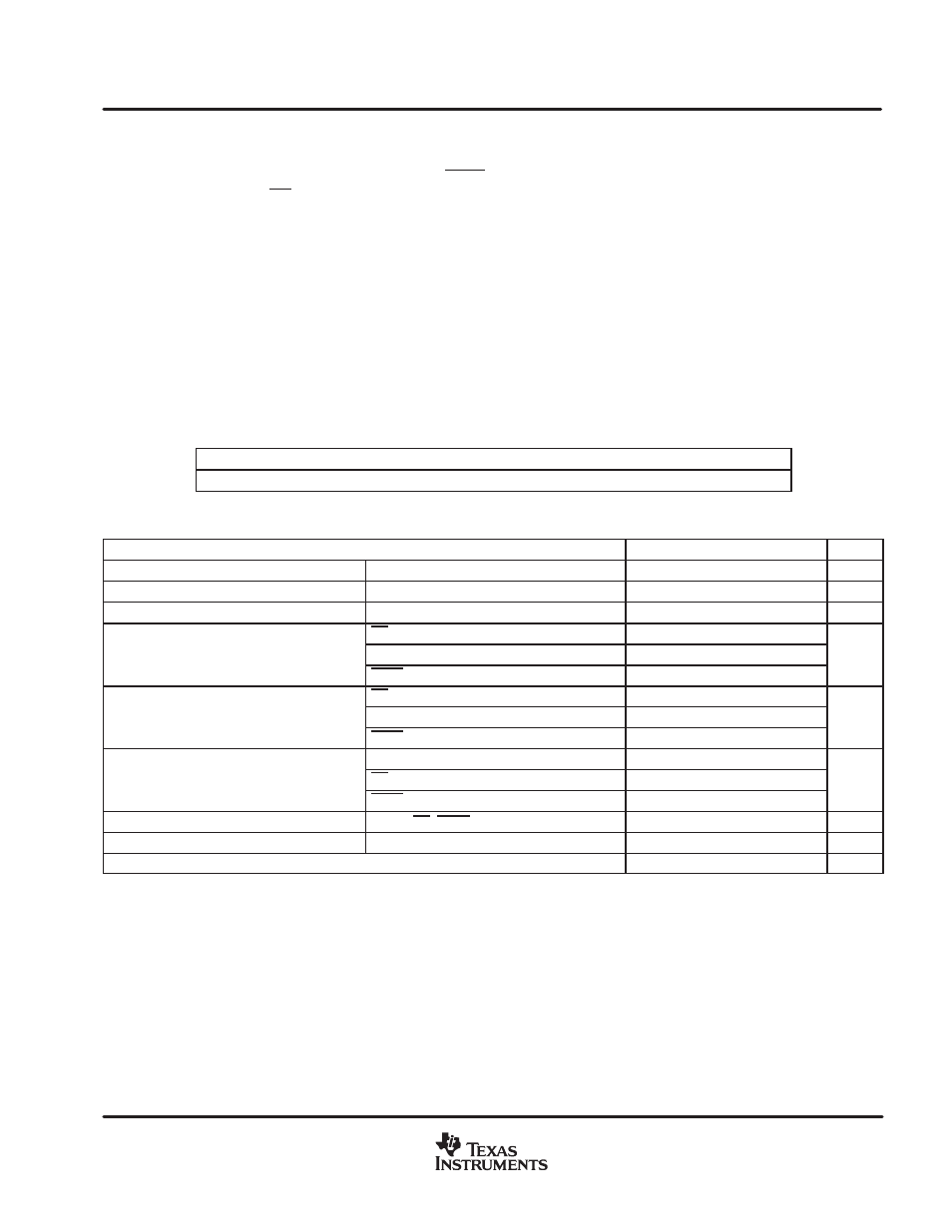
recommended operating conditions
MIN
MAX
UNIT
Supply voltage, VCC
PVCC, AVCC
8.5
14
V
Volume reference voltage
VREF
3.0
5.5
V
Volume control pins, input voltage
VOLUME
5.5
V
SD
2
High-level input voltage, VIH
MUTE
3.5
V
High-level input voltage, VIH
FADE
4
V
SD
0.8
Low-level input voltage, VIL
MUTE
2
V
Low-level input voltage, VIL
FADE
2
V
MUTE, VI= 5 V, VCC = 14 V
1
High-level input current, IIH
SD, VI= 14 V, VCC = 14 V
50
µ
A
High-level input current, IIH
FADE, VI= 5 V, VCC = 14 V
150
µ
A
Low-level input current, IIL
MUTE, SD, FADE, VI= 0 V, VCC = 14 V
1
A
Low-level input current, IIL
MUTE, SD, FADE, VI= 0 V, VCC = 14 V
1
µ
A
Oscillator frequency, fOSC
225
275
kHz
Operating free-air temperature, TA
−40
85
°
C