Texas Instruments TPA3003D2 User Manual
Page 16
TPA3003D2
SLOS406A − FEBRUARY 2003 − REVISED MARCH 2003
16
www.ti.com
APPLICATION INFORMATION
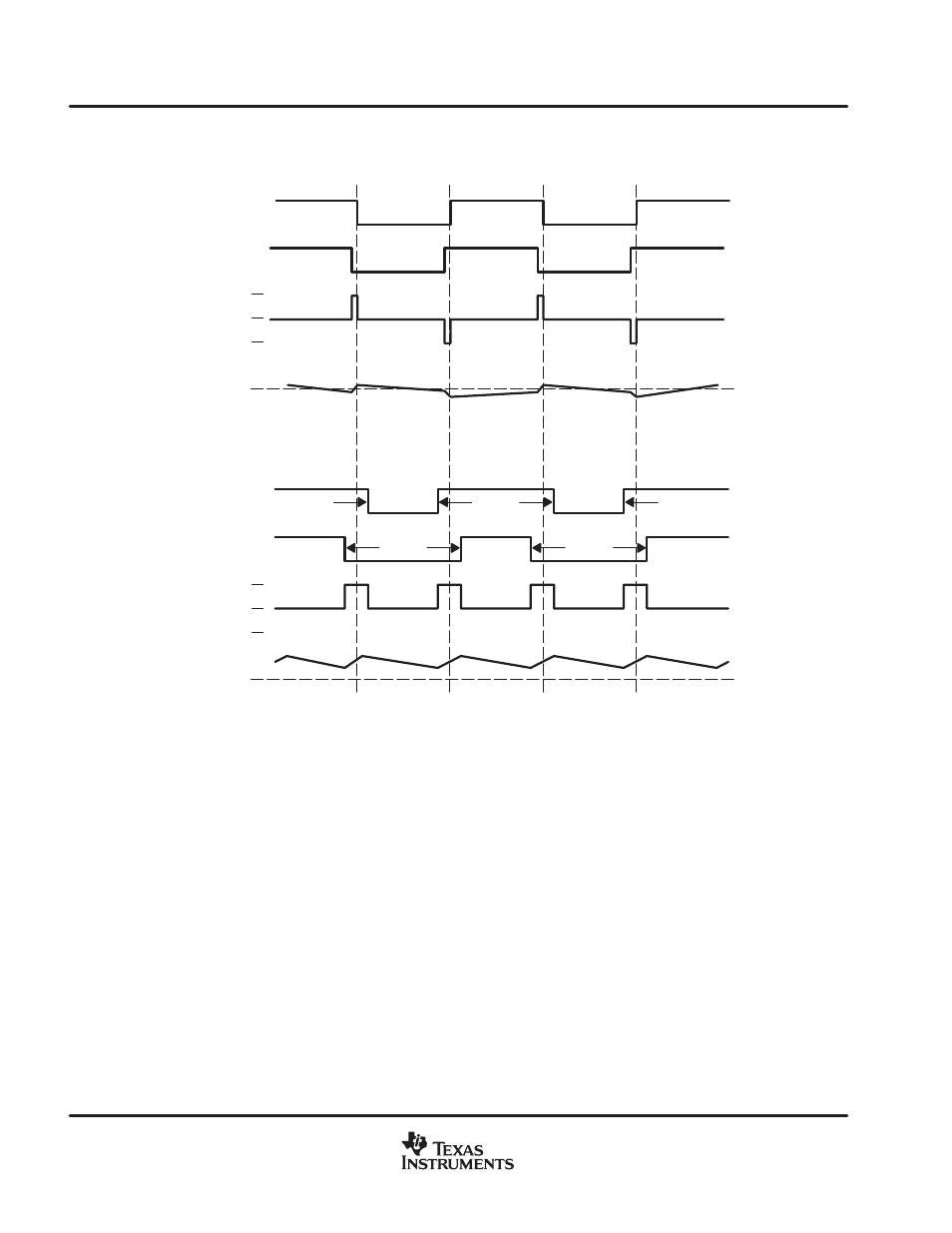
TPA3003D2 modulation scheme (continued)
0 V
−12 V
+12 V
Current
OUTP
OUTN
Differential
Voltage
Across
Load
0 V
−12 V
+12 V
Current
OUTP
OUTN
Differential
Voltage
Across
Load
Output = 0 V
Output > 0 V
Figure 23. The TPA3003D2 Output Voltage and Current Waveforms Into an Inductive Load
efficiency: LC filter required with the traditional class-D modulation scheme
The main reason that the traditional class-D amplifier needs an output filter is that the switching waveform
results in maximum current flow. This causes more loss in the load, which causes lower efficiency. The ripple
current is large for the traditional modulation scheme, because the ripple current is proportional to voltage
multiplied by the time at that voltage. The differential voltage swing is 2
×
V
CC
, and the time at each voltage is
half the period for the traditional modulation scheme. An ideal LC filter is needed to store the ripple current from
each half cycle for the next half cycle, while any resistance causes power dissipation. The speaker is both
resistive and reactive, whereas an LC filter is almost purely reactive.
The TPA3003D2 modulation scheme has very little loss in the load without a filter because the pulses are very
short and the change in voltage is V
CC
instead of 2
×
V
CC
. As the output power increases, the pulses widen,
making the ripple current larger. Ripple current could be filtered with an LC filter for increased efficiency, but for
most applications the filter is not needed.
An LC filter with a cutoff frequency less than the class-D switching frequency allows the switching current to flow
through the filter instead of the load. The filter has less resistance than the speaker, which results in less power
dissipation, therefore increasing efficiency.