Note, Figure 12: transition and conduit locations, Hang hood from screws and tighten securely – Thermador PROFESSIONAL PH PH54 User Manual
Page 11: Centerline hole dimensions for figures 11 and 12, Blower preparation, Figure 13: blower front view, Figure 14: blower rear view, Figure 12 to crea, Sion b in figure 12
English 9
3. For horizontal discharge, use Figure 6 for the geometry
of the cutout required for clearance of the transition.
4. Hang hood from screws and tighten securely.
5. From inside of hood, insert screws supplied. Drill
through holes (use #8 x 5/8" screws supplied), one (1)
on each side and four along the front, into bottom of the
cabinet. See screw holes labeled "L" in Figure 11.
Centerline Hole Dimensions for Figures 11 and 12
Installing an Integral Blower,
Model VTN630C or VTN1030C
The hood can be installed with a model VTN630C or
VTN1030C integral blower.
Blower Preparation
1. Remove left and right shipping brackets and discard.
2. Cut wire tie shown in Figure 13. Locate the wire
harness with the Molex 6-pin connector. Route wire
harness out rear of blower, as shown in Figure 14
below.
3. Re-attach wire harnesses to capacitor with new wire tie
(supplied) in same location in front.
4. Attach wire harness with Molex 6-pin connector to
housing as shown in Figure 14 with wire tie (supplied).
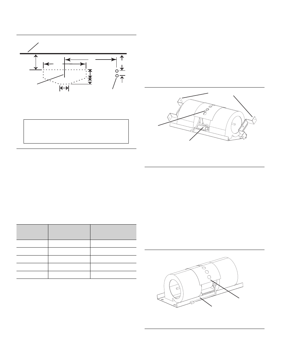
Figure 12: Transition and Conduit Locations
HOOD
SIZE
A (Fig 11)
Tap Holes
B (Fig 12)
Conduit Holes
30”
29-1/16”
13-7/16”
36”
35-1/16”
16-7/16”
42”
41-1/16”
19-7/16”
48”
47-1/16”
22-7/16”
54”
53-1/16”
25-7/16”
23"
3-3/16"
7-7/8"
2-3/8"
Wall
B
1-1/8"
1-7/8"
2-3/8"
Cooktop
Centerline
Plan View of Cabinet Cutout
5/8" DIA clearance
holes for 1/2" conduit
to j-box.
Note:
This figure depicts transition and conduit
locations only. See Figure 2 on page 4 for overall
hood dimensions.
Figure 13: Blower Front View
Figure 14: Blower Rear View
Shipping Brackets
Blower Front View
Capacitor
Wire tie
Wire
Harness
Blower Rear View
Add wire
tie here