Notice – The New Yorker Store Cast Iron-Oil Fired Boiler CL User Manual
Page 12
12
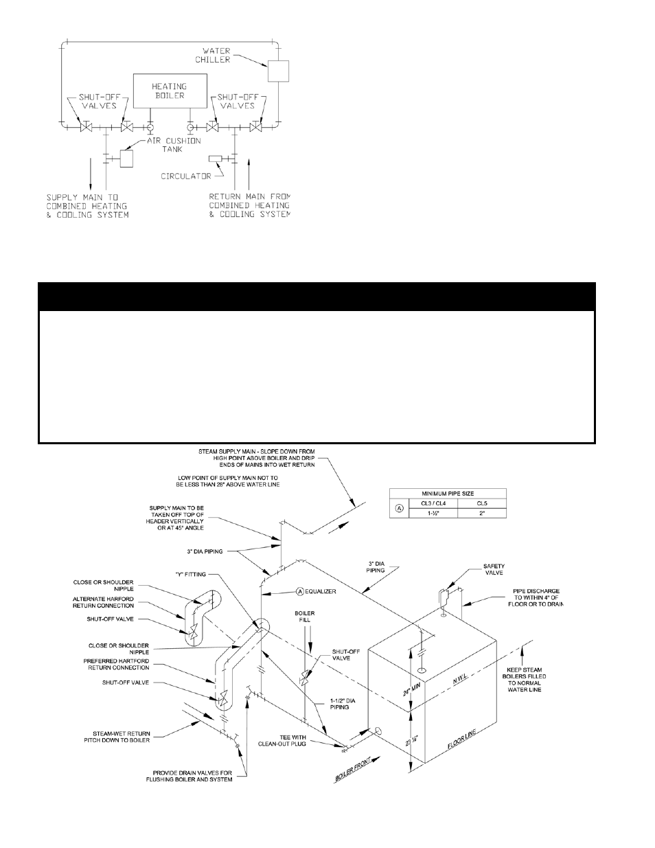
Figure 10: Recommended Piping for Combination
Heating & Cooling (Refrigeration) Systems
Figure 11: Recommended Boiler Piping For Gravity Return Steam Boiler
2. Install ¾" drain valve in wet return piping as shown
in Figure 11.
3. On boilers with rear tankless heater, factory wired
L4006A Aquastat Heater Control was not installed
in heater. Locate ¾" NPT Immersion Well, apply
sealant and thread into ¾" NPT tapping on heater.
Apply heat transfer paste (not furnished) to control
bulb and insert bulb into immersion well. Tighten
clamping screws to secure control to immersion
well. Secure 18/2 Control Cable Wire to jacket right
side panel with 5/16" cable clamp provided, refer to
Figure 1C.
4. CONNECT FIELD WIRING
a. Connect the field wiring to the pressure limit,
the R8239C Control Center, the LWCO and
the burner primary control. If equipped with
tankless heater, connect field wiring from the
aquastat control to the R8239C Control Center's
"R-G" terminals. Make the wiring connections
as shown in Figure 19B.
NOTICE
Before using copper for steam piping, consider the following characteristics of copper piping:
1) High coefficient of thermal expansion can induce mechanical stresses and cause expansion/
contraction noises if not accounted for in the piping system design and installation,
2) High heat transfer rate (heat loss) of un-insulated copper piping must be included in the normal piping
and pickup factors used to size the boiler,
) Soldering or brazing pastes and fluxes that end up in the system can cause poor heat transfer, surging,
an unsteady water line and wet steam if not thoroughly removed during boil out procedure and,
) Galvanic corrosion of the adjoining metal may occur due to dissimilar metals in certain water chemistries
if dielectric unions are not used.