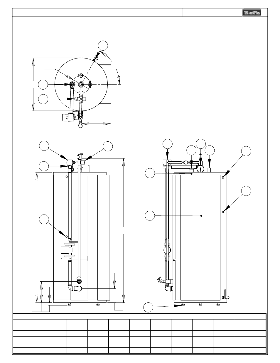
Figure 2 page 3 – Thermo Products COMBOMAX Models from 8 kW to 24 kW : 240 Volts ( single phase ) User Manual
Page 3
13
6
5
10
12
3
16
8
9
F
4
7
1
I
G
H
C
B
D
E
A
2
11
14
15
THERMO 2000 inc.
DESSIN D'ATELIER / GENERAL DIMENSIONS COMBOMAX XX-XX
Legeng/Légende:
1) Boiler Water Supply Connection /
Alimentation du chauffage (1" npt F)
2) Boiler Water Return/
Retour du chauffage (1" npt F)
3) Domestic Water inlet /
Entrée eau domestique (3/4" Sweat F)
4) Domestic Water outlet/
Sortie eau domestique (3/4" Sweat F)
5) Safety relief valve/
Soupape de sûreté (3/4" npt M.)
6) Temperature and pressure Gage/
Indicateur de Température et pression (1/2'' npt. M)
7) Drain Valve/
Valve de drainage (3/4'' npt F)
8) Power supply wiring/
Alimentation électrique
9) Pilot Lights/
Lampe témoin
10) Electrical Compartments/
Compartiment électrique
11) Circulator wiring/
Alimentation pompe
12) Thermostat wiring/
Connection thermostat
13) Air vent/
Purgeur d'air
14) Valve 3 voies/
3 ways valve
15) Valve thermostatique/
Thermostatic mixing valve
16) Adjustable leg/
Patte de support
Modèle/
A
B
C
D
E
F
G
H
I
Model
in.
in.
in.
in.
in.
in.
in.
in.
degrés/degree
COMBOMAX 23-XX
49 3/16
42 1/4
7 1/4
4
1
18
10 1/2
8
75
COMBOMAX 34-XX
65 1/2
59
7 1/4
4
1
18
10 1/2
8
75
COMBOMAX 44-XX
57 3/4
49 1/2
9 1/2
5 3/4
1
22
12 1/2
8
60
COMBOMAX 64-XX
65 1/2
58 1/2
9 1/2
6 1/2
1
24
13 1/2
8
60
DIMENSION/ DIMENSIONAL
Figure 2
Page 3