Therma-Stor Products Group HI-E Dry Vehere User Manual
Page 5
5
www.thermastor.com • [email protected]
Toll-Free 1-800-533-7533
Controller
If the Vehere is to be located in a remote location outside
the pool or spa area, mounting of the humidity sensor in the
space to be conditioned is necessary. If the humidity sensor
is not located in the conditioned space, the Vehere will not
operate properly.
IMPORTANT: Locate the humidity element on an inside wall, free
from drafts, out of direct sunlight, and where the element is not
exposed to excessive vibration. Be careful not to drop the unit.
Mount the wall mount element at a height of 4 to 6 feet (1.2 to
1.8 m) above the floor.
To mount the HI-E DRY Vehere dehumidistat on a wall for
remote application, first remove the cover from the controller
by lifting the side of the controller cover over the catch tabs
on both sides. The cover comes off easily.
Hold the unit to the surface you would like to mount it on. You
will need to mark the locations for two screw holes and one
square knockout to accommodate wires and the devices wire
guard. The wire-guard tabs fit inside the wall. (See Fig. 6, 7)
Once marked, drill a 1/8” hole for each mounting screw
location and tap the provided anchor mount into the hole.
Use the provided screws to then mount the humidity
control to the wall. Route the wiring through the hole you
have created and connect wires according to the directions
found in this manual. Replace plastic housing.
3.3 Electrical Requirements
The Vehere can be plugged into any grounded 20 Amp circuit.
At 80°F, 60% RH, it draws 12 Amps. A dedicated 20 Amp
circuit is recommended.
3.4 Condensate Removal
Condensate drains by gravity via the clear hose extending
from the unit. Route the 4’ drain hose to a floor drain. Use
care to keep the hose as flat to the floor as possible. Keep
the hose away from walk ways if possible. Excessive humps
or kinks will prevent proper drainage. If the Vehere is located
too far from a floor drain for the attached hose to reach,
inexpensive 1/2” PVC pipe can be used to extend it. It is
commonly available in 10’ lengths from building supply,
plumbing and hardware stores. It will slide tightly inside the
end of the drain hose. If more than one length of pipe is
required, they can be joined with a short piece cut from the
end of the drain hose.
3.5 Ducting
3.5A Ducting kit
The factory installation kit includes two twelve-inch collars
to allow ducting to be attached to the inlet and outlet of
the Vehere. The 12” collar with three tabs can be attached
via the holes provided in the front of the unit, and the 12”
flanged collar can be affixed to the top opening. S (See Fig. 8)
3.5B Ducting for Dehumidification
Ducting the Vehere as mentioned requires consideration of
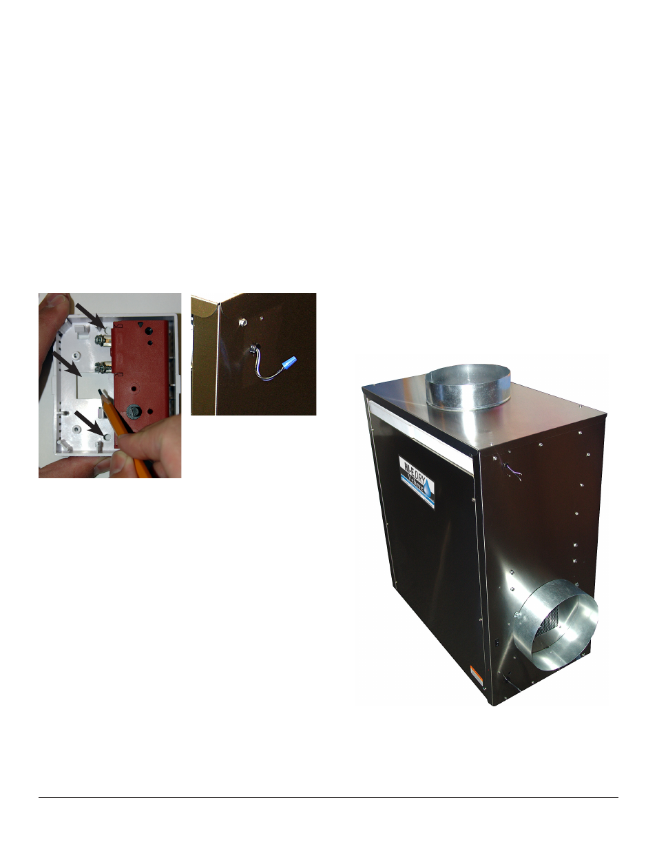
Figure 6: Mark mounting
holes as indicated by arrows.
Figure 7: Control
connection wires.
Figure 8: Tabbed duct collar is installed around the exhaust
outlet. The flanged duct collar is installed around the intake
opening.
Tabbed duct collar
Flanged duct
collar