Caution, Important – TOA Electronics CST38MH User Manual
Page 18
NOTE: DIAGRAMS & ILLUSTRATIONS ARE NOT TO SCALE.
18
If you’re installing a gas line, connect it before
the fireplace is framed and enclosed in the
finished wall. The gas knockout is determined
by a 1-1/8" (29 mm) round indentation located
at the bottom and slightly off center in the
side refractories. The KnocKouT Is always
remoVed from InsIde The fIrePlace. do
noT remoVe The KnocKouT unless you
are InsTallInG a Gas lIne. If removal is at-
tempted from the outer wrapper, side-refractory
damage may occur. With a medium-sized ham-
mer, lightly tap the surface of the indentation.
The refractory material is very thin in this area
and is easily removed. Once a small hole has
been made, continue tapping until you have
reached sufficient diameter for the gas line to
fit through. The entire knockout does not have
to be removed. Remove insulation in the gas
line channel.
Install a 1/2" (13 mm) gas supply line through
fireplace wall for connection to a decorative
gas appliance inside the firebox. Outside, the
gas supply line must connect to a gas shut-off
valve usually recessed flush into the wall or floor.
The valve should be controlled by a removable
valve key for safety.
Always plumb gas line installation per local
codes. Check all connections using a gas leak
test solution (also referred to as bubble leak
solution). Note: Using a soapy water solution
(50% dish soap, 50% water) is an effective
leak test solution but it is not recommended,
because the soap residue that is left on the
pipes/fittings can result in corrosion over time.
Never test any gas line connection with a match
or open flame.
hearth extensions and wall shields
A hearth extension must be installed with all
fireplaces. Its purpose is twofold. It protects a
combustible floor in front of the fireplace from
both radiant heat and sparks and it distinguishes
the prescribed hearth extension area from other
non-protected surfaces.
The hearth extension must extend beyond
the front and both sides of the fireplace side
openings. Use a hearth extension constructed
of a durable noncombustible material having
an equal or better (lower k value) insulating
value of k = .84 BTU IN/FT
2
HR °F or a thermal
resistance that equals or exceeds r=1.19 HR
°F FT
2
/BTU IN. A minimum 3/8" (10 mm) thick
noncombustible material is all that is required
over a noncombustible or slab floor.
If there is a continuous perpendicular side
wall closer than 18" (mm) from the fireplace
opening, it must be protected with a 40" x 40"
x 1/2" (1016 mmx 1016 mm x 13 mm) wall
shield (see Figure 46) constructed of a durable,
noncombustible material having an equal or
better (lower k value) insulating value than k =
.84 BTU IN/FT
2
HR °F. A continuous protected
side wall can not be closer than 8" (203 mm)
from the fireplace opening.
Secure the hearth extension to the floor to
prevent possible shifting.
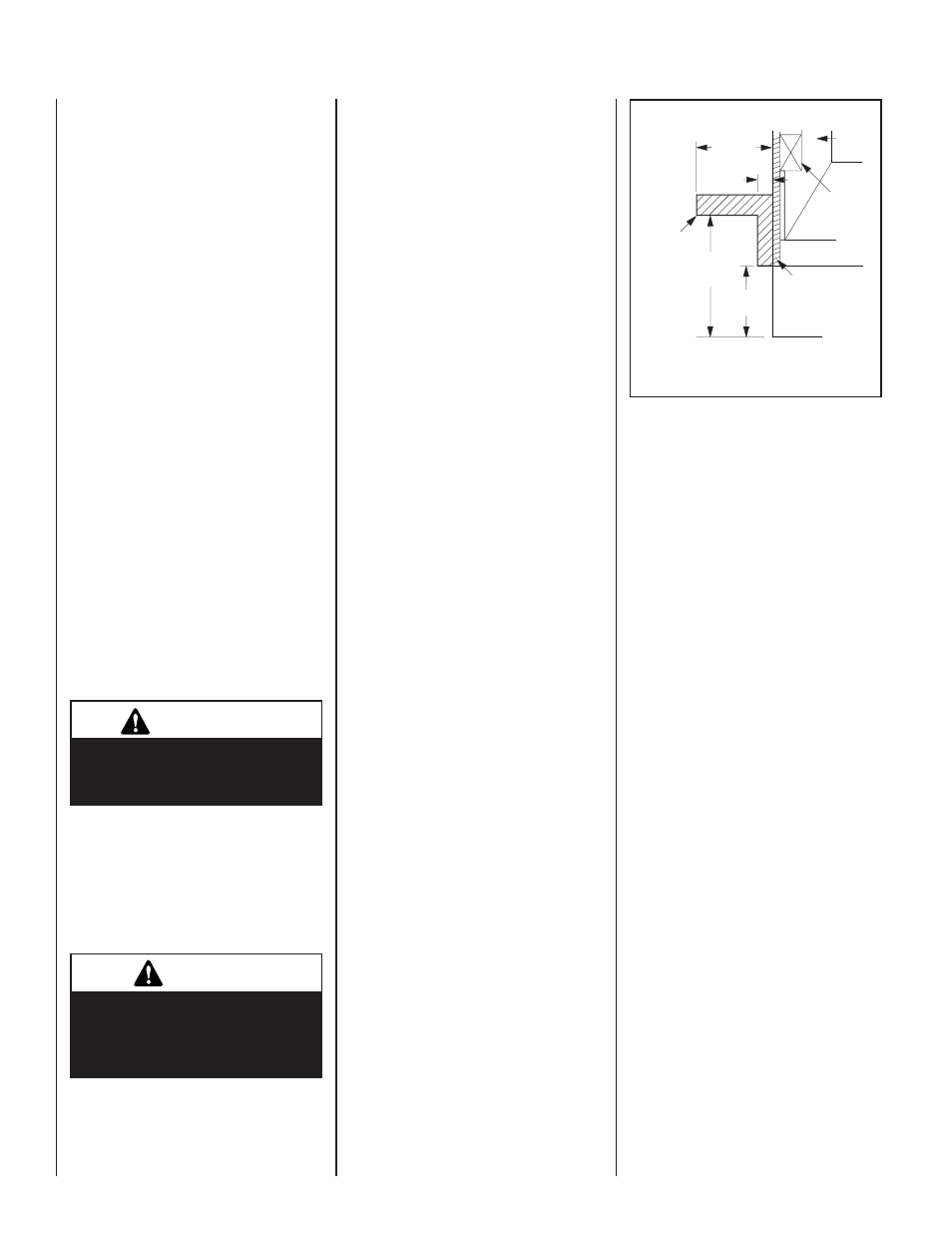
12"
(305 mm)
Min.
6"
(152 mm)
Finished Wall
Spacer
Combustible
Mantel
and Trim
12"
(305 mm)
Max.
False
Header
Typical U.S. Installation
1 ¹⁄₂"
(38 mm)
Fireplace Opening
cauTIon
when using the decorative gas
appliance, the fireplace damper
must be set in the fully open
position.
For all areas, this provision is intended only
for connection to a decorative gas appliance
incorporating an automatic shut-off device and
complying with the standard for Decorative Gas
Appliances for installation in vented fireplaces,
ANSI Z21.60. Install in accordance with the
National Fuel Gas Code, ANSI Z223.1.
ImPorTanT
repack insulation material in
square hole around gas line,
interior and exterior, to seal.
Figure 45 - Mantel Clearances
cold clImaTe InsulaTIon
If you live in a cold climate, it is especially
important to seal all cracks around the fire-
place and wherever cold air could enter the
room with noncombustible material. Surround
material must be caulked where it meets the
black metal facing of the fireplace to avoid
cold air intrusion. Use noncombustible caulk-
ing material only on fireplace facing to seal.
Also, the outside air inlet duct should be
wrapped with noncombustible insulation to
minimize the formation of condensation. Do
not place insulation materials directly against
the chimney sections.
Note: 2" (51 mm) air space must be preserved
for all materials extending for any continuous
length adjacent to the chimney.
It is especially important to insulate between
the studs of an outside chase cavity and under
the floor if the floor is above ground level. Do
not place insulation directly against the fireplace
or chimney system.
fIrePlace fInIshes
mantels and Trim
It is sometimes best to frame your fireplace af-
ter it is positioned and the chimney is installed.
Frame enclosure for chimney and fireplace with
2 x 4’s (or heavier) lumber.
Note: The header may rest on the two (2) metal
top spacers on top of the unit but the header must
not be notched to fit around the spacers.
In all installations, combustible mantels and
trim may be installed 12" (305mm) above the
opening as per NFPA 211-latest edition. and
Figure 45. If a mantel is of a noncombustible
material, it is exempt from the requirements as
long as it does not interfere with the operation
of glass doors.