Warning – TOA Electronics CST38MH User Manual
Page 10
NOTE: DIAGRAMS & ILLUSTRATIONS ARE NOT TO SCALE.
10
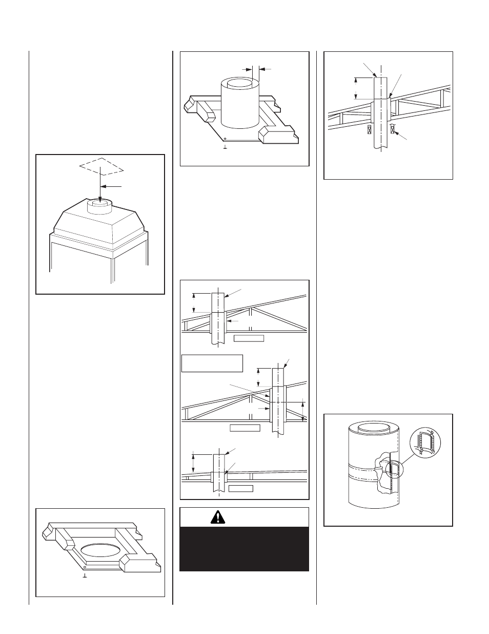
For new construction, to determine chimney
center line, use plumb line from roof or ceil-
ing above fireplace to center of flue collar on
fireplace.
For remodeling, plumb to center of flue collar
from ceiling above, drive nail through ceiling
from below to mark position, then mark and
cut to passage from above ceiling (around nail)
(Figure 19). Then plumb from ceiling or roof
level directly above hole which has just been
completed.
Plumb line
step 3. Position appropriate thimble/firestop
spacer combination at ceiling and nail
temporarily with two (2) 8d nails or
equivalent fasteners (see Figures 21, 22
and 23). Use thimble/firestop spacer,
model FM8-AT2, if chimney penetrates
ceiling vertically. If chimney penetrates
ceiling at 30˚ angle (offset) chimney use
Model F8FS30-2. Use one fastener on
opposite sides to hold thimble/firestop
spacer combination in position. Nail
permanently, using at least two (2) more
fasteners, after chimney sections have
been assembled through the thimble/
firestop spacer combination and after any
necessary adjustments have been made.
Firestop spacer must be secured by at
least four (4) fasteners when completely
installed.
Note: If there is a room above ceiling level,
firestop spacer must be installed on the bottom
side of the ceiling. If an attic is above ceiling
level, firestop spacer must be installed on top
side of ceiling joist (Figure 20).
Firestop Spacer
F8FS-2
Room Above
Figure 20
Figure 19
Firestop Thimble
FM8-AT2
Attic Above
2”
Clearance
Minimum
Figure 21
Ensure the thimble penetrates the roof opening.
The thimble must extend completely through the
ceiling or roof cavity to the outermost plane of
the roof. Note: Thimble extensions (F8-TE26-2)
are available from your dealer for constructions
in which the distance between the outside of the
roof and the inside of the ceiling exceeds 13".
The thimbles and their extensions provide for
zero clearances to combustibles and must be
used at the ceiling/roof in manufactured homes
(Figures 22 and 23).
Figure 22
Note: Trim Thimble/
Extension To Desired Length
And Pitch At The Rood Line
14" Min.
Pitched Roof
Pitched Roof
Bow Roof
14" Min.
Outer Pipe Of
Chimney
Outer Pipe Of
Chimney
Outer Pipe Of
Chimney
14" Min.
Thimble
FM8-AT2
13"
Thimble
FM8-AT2
Thimble
FM8-AT2
Thimble
Extension
F8-TE26-2
warnInG
do not allow insulating materials to
be blown into the space inside the
thimble and the chimney. To do so
could result in a fire hazard.
Thimble Cathedral
Ceiling
14" Min.
Outer Pipe Of
Chimney
Use Adjustable Thimble
FM8-AT2 For All Ceiling
Piches, From Flat To
3/12 Pitch.
Figure 23
step 4. Note: Chimney sections are con-
structed with a unique locking tab
design, which ensures an immediate,
tight assembly between sections. Plan
your chimney requirements carefully
before assembly as chimney is difficult
to disassemble after installation. If
disassembled, the tabs might become
damaged. Be certain tabs are properly
formed to ensure locking tabs engage
properly.
The Security Chimneys FTF8 chimney system
is a two piece chimney, which snap together
from the fireplace up. Start with the inner flue
section with the lanced end up, snap lock it in
to the matching collar on top of the fireplace.
At all subsequent joints, the upper flue section
fits into the preceding flue section. Each piece
snaps together by means of locking tabs (9
locking tabs per joint). Check each piece by
pulling up slightly from the top to ensure proper
engagement before installing the next section.
If the flue has been installed correctly, it will not
separate when you test it. Also, the inner flue
joint where each section is joined should be
tight and flat without gaps (Figure 24).
Figure 24
Outer pipe section installs in just the opposite
way; the lanced end goes down and each new
section goes OVER the outside of the previous
section installed (Figure 25).