Reference reset circuit, Figure 7 - reset circuit, 1 reference reset circuit – Quatech 802.11B/G User Manual
Page 33
Airborne Enterprise Module Databook
Quatech, Inc.
100-8080-120
7/15/2010
33
9.1
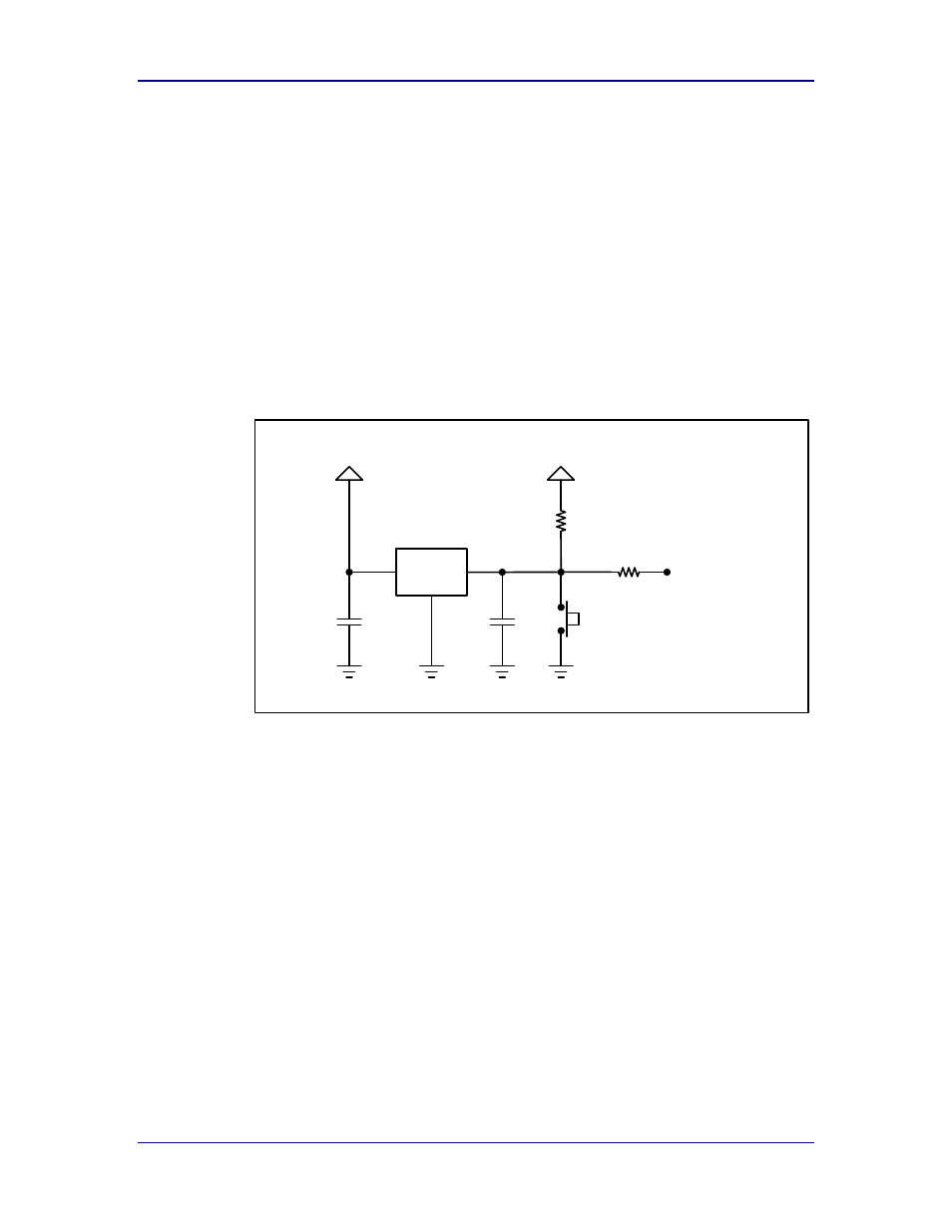
Reference RESET Circuit
Proper control of the RESET signal is required, if not controlled correctly the
power-on sequence of the module can be impacted and correct booting
impacted. It is recommended that where possible the RESET signal of the
module should be controlled by an external controller (MCU, POR controller).
Where control of the RESET signal by system level monitor is not possible
Quatech recommend the use of the circuit in Figure 7, or one similar. This circuit
controls the RESET signal relative to power supply to the module and delays
release of the RESET until a valid power supply is detected.
Figure 7 - RESET Circuit
MCP120T-300
/RESET (pin 7)
R1
33KΩ
C1
0.01µF
SW
Momentary ON/OFF
C2
0.1µF
R2
22KΩ
V
DD
+3.3VDC
V
DD
/RST
V
SS
The circuit also includes a manual RESET option should this be required. This
manual RESET option can be used with the Factory RESET input (pin11) as a
hardware factory REST option.