Spi interface, Pinout, Table 11 - spi pinout details – Quatech 802.11B/G User Manual
Page 21: Table 12 - spi signal descriptions, 0 spi interface, 1 pinout
Airborne Enterprise Module Databook
Quatech, Inc.
100-8080-120
7/15/2010
21
7.0 SPI Interface
The following section details the SPI interface specification for both hardware timing and
SPI protocol. The device is a SPI slave and requires a compatible SPI master for
operation.
7.1
Pinout
When the SPI interface is enabled, through the CLI or web interface, the
following pins are assigned for communication.
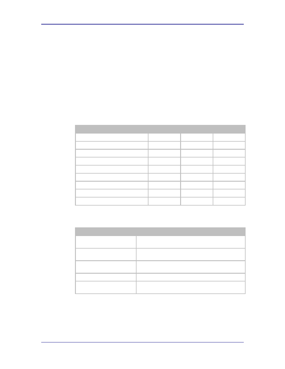
Table 10 - SPI Pinout Details
Pin Definition
SPI
UART2 Pin
Debug
Master In Slave Out (MISO)
28
Master Out Slave In (MOSI)
24
SPI Interrupt (SPI_INT)
22
SPI Clock (SPI_CLK)
18
SPI Select (/SPI_SEL)
12
Data In (RxD2, DTXD)
9
8
Data out (TxD2, DRXD)
21
6
Ready-to-Send (RTS2)
17
Clear-to-Send (CTS2)
19
Table 11 - SPI Signal Descriptions
Pin Definition
Description
Master In Slave Out (MISO)
Serial Data OUT; must be connected to the serial data in of
the master.
Master Out Slave In (MOSI)
Serial Data IN; Must be connected to the serial data out of the
master.
SPI Interrupt (SPI_INT)
Interrupt signal driver by slave see Table 15 for details of
operation.
SPI Clock (SPI_CLK)
SPI clock sourced from the master.
SPI Select (/SPI_SEL)
Enable the SPI slave, sourced from the master. Active low
signal.