Modbus cable pinouts – Quantum 890 USE 155 User Manual
Page 24
Installing the Bridge Hardware
24
2.5
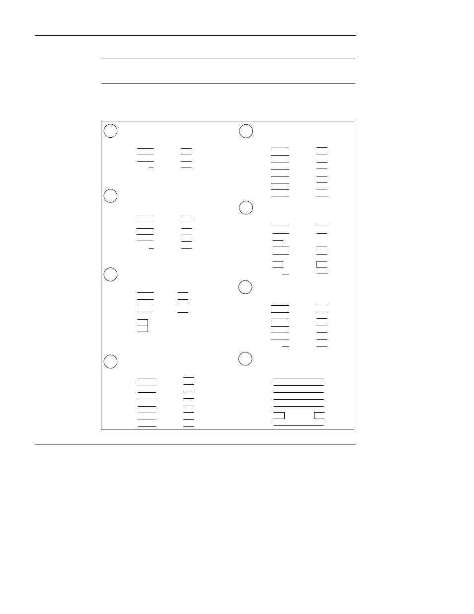
Modbus Cable Pinouts
References in this figure are to the devices listed in Table 8 on page 23.
Figure 8
Modbus Cable Pinouts
Adapter Kit: 110 XCA 203 01
DB9M
Wire
RJ45
2
Red
4
3
Black
3
5
Green
5
Shield
White
8
Adapter Kit: 110 XCA 203 01
DB9M
Wire
RJ45
1
Black
3
4
Red
4
5
Green
5
6
Yellow
6
9
Brown
7
Shield
White
8
A
B
C
D
E
F
G
Adapter Kit: 110 XCA 204 01
DB25M
Wire
RJ45
1
White
8
2
Red
4
3
Black
3
7
Green
5
4
6
20
Adapter: None
RJ45 (Prog)
RJ45 (Bridge)
1
2
2
1
3
4
4
3
5
5
6
6
7
7
8
8
Adapter Kit: 110 XCA 204 01
Adapter Kit: 110 XCA 203 02
DB9F
Wire
RJ45
2
Red
4
3
Black
3
4
6
Orange
2
5
Green
5
7
6
8
7
Shield
White
8
DB9M
Wire
RJ45
2
Red
4
3
Black
3
5
Green
5
6
Orange
2
7
Yellow
6
8
Brown
7
Shield
White
8
Adapter Kit: 110 XCA 203 01
DB25M
Wire
RJ45
3
Red
4
2
Black
3
20
Blue
1
7
Green
5
6
Orange
2
4
Yellow
6
5
Brown
7
1
White
8
H
Adapter Kit: 110 XCA 204
01
DB25M
Wire
RJ45
2
Red
4
3
Black
3
6
Blue
1
7
Green
5
20
Orange
2
5
Yellow
6
4
Brown
7
1
White
8