Calibrator interface – Omega PCL340 User Manual
Page 8
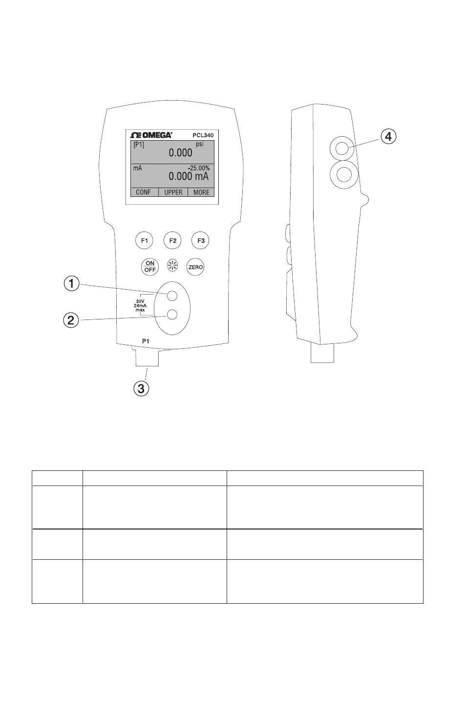
2. Calibrator Interface
Figure 1 shows the location of the process measurement inputs,
while table 1 describes their use.
Figure 1
Process Measurement Inputs
Table 1 Process Measurement Inputs
No. Name
Description
1, 2
Input Terminals
These terminals are used to
measure current, voltage and a
contact closure for switch test.
3
P1 Pressure Port
This is the connection for the
internal sensor P1
4
Serial Interface
This is used to interface to optional
external modules or optional serial
control.
Figure 2 shows the location of the keys. Table 2 describes the
function of each key.
4
Side View
This manual is related to the following products: