Connecting the connectors and ac outlets, Connections – Onkyo R-801A User Manual
Page 12
12
Connecting to the ONKYO Separate Collection Series components
Before connecting
• The hookups on page 11 is needed in addition to the
(for remote control operations)
and AC OUTLET (for power supply to each component) hookups on this page.
• Each component has two
connectors. There is no difference between those connectors.
The components may be connected in any order.
• The
remote control cable for connecting the
connectors is supplied with each com-
ponent (not supplied with the unit).
Connections
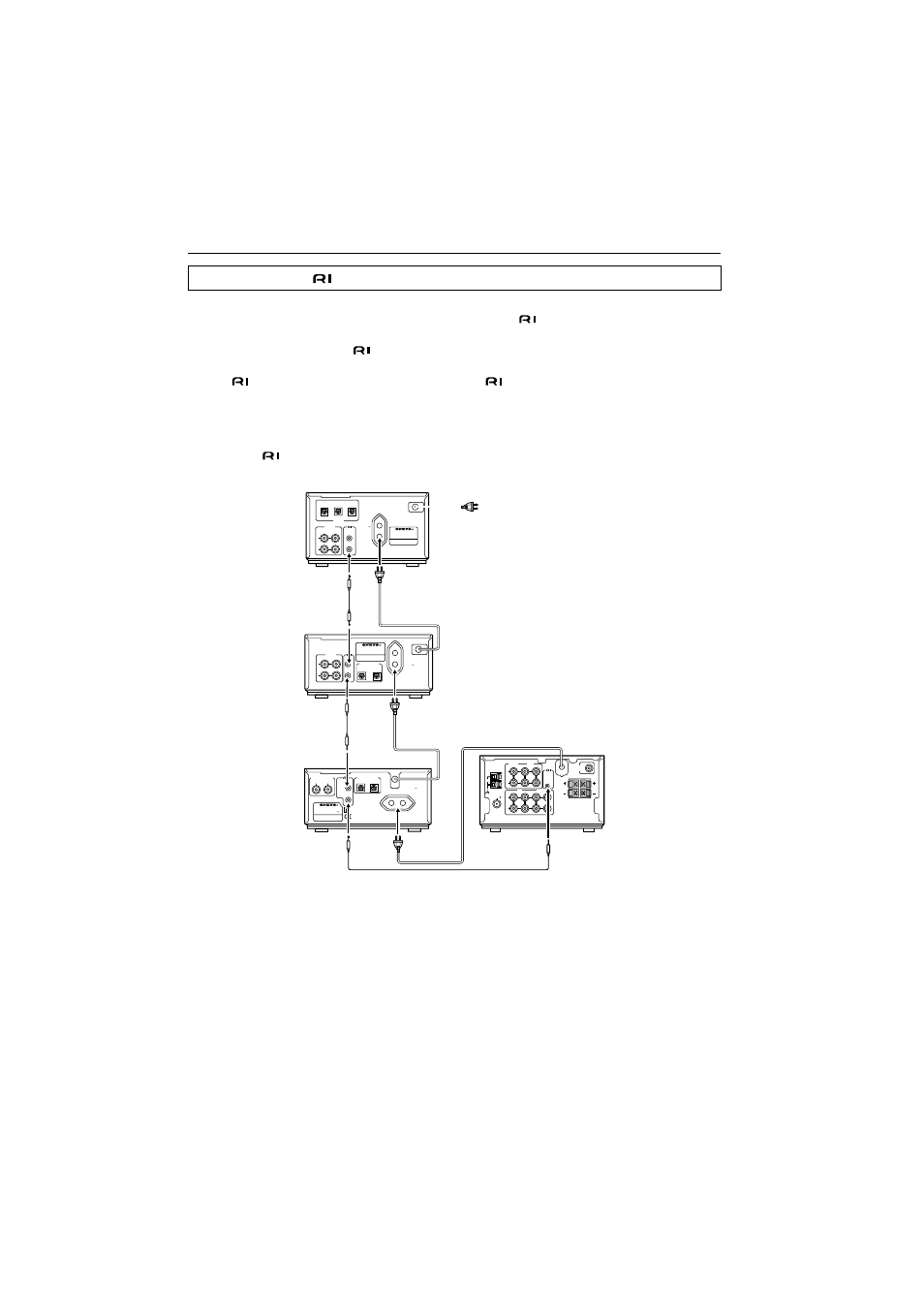
To use the Clock/Timer function of this unit’s, connect the power cord as shown below and
connect the
remote control cable and audio connection cables (see page 11). Be sure to
connect the power cord of this unit to an AC outlet that supplies continuous power.
Connecting the
connectors and AC OUTLETS
L
R
ANALOG OUTPUT
DIGITAL OUTPUT
REMOTE
CONTROL
OPTICAL
MODEL NO.
C-701A
RATING: AC 230-240 V
50 Hz 8 W
COMPACT DISC PLAYER
AC OUTLET
AC 230-240 V 50 Hz
UNSWITCHED
100 W MAX.
L
R
ANALOG
REMOTE
CONTROL
INPUT
OUTPUT
OPTICAL
DIGITAL
INPUT
1
INPUT
2
OUTPUT
MODEL NO.
CDR-201A
AUDIO CD RECORDER
AC OUTLET
AC 230-240 V
50 Hz
UNSWITCHED
100 W MAX.
L
R
ANALOG
REMOTE
CONTROL
INPUT
OUTPUT
OPTICAL
1
2
DIGITAL INPUT
MINIDISC RECORDER
MODEL NO.
MD-101A
AC OUTLET
AC 220
-230 V
50 / 60 Hz
UNSWITCHED
100 W MAX.
CD/DVD
TAPE
OUT
IN
IN
OUT
IN
OUT
IN
MD
CDR/PC
ANTENNA
AM
FM 75
REMOTE
CONTROL
SPEAKERS
L
R
L
R
SUBWOOFER
PRE OUT
R
L
R
L
CAUTION:
SPEAKER
IMPEDANCE
4 OHMS MIN.
/ SPEAKER
This unit (R-801A)
CD player (C-701A)
To wall outlet
MD recorder
(MD-101A)
CD recorder
(CDR-201A)