Rear panel facilities – Onkyo TX-DS797 User Manual
Page 13
13
PRE OUT
FRONT
SUB
SURR
CENTER
R
L
SURR
BACK /
MULTI C
INPUT
FRONT
2
3
1
DIGITAL
OUTPUT
OPT
COAX
DIGITAL
INPUT
Front input
Surround input
Surround
back
Center
Subwoofer
R (red)
L (white)
R (red)
L (white)
R (red)
L (white)
8
7
6
5
4
3
2
1
ANTENNA
These jacks are for connecting the FM indoor antenna and AM loop
antenna that are supplied with the TX-DS797.
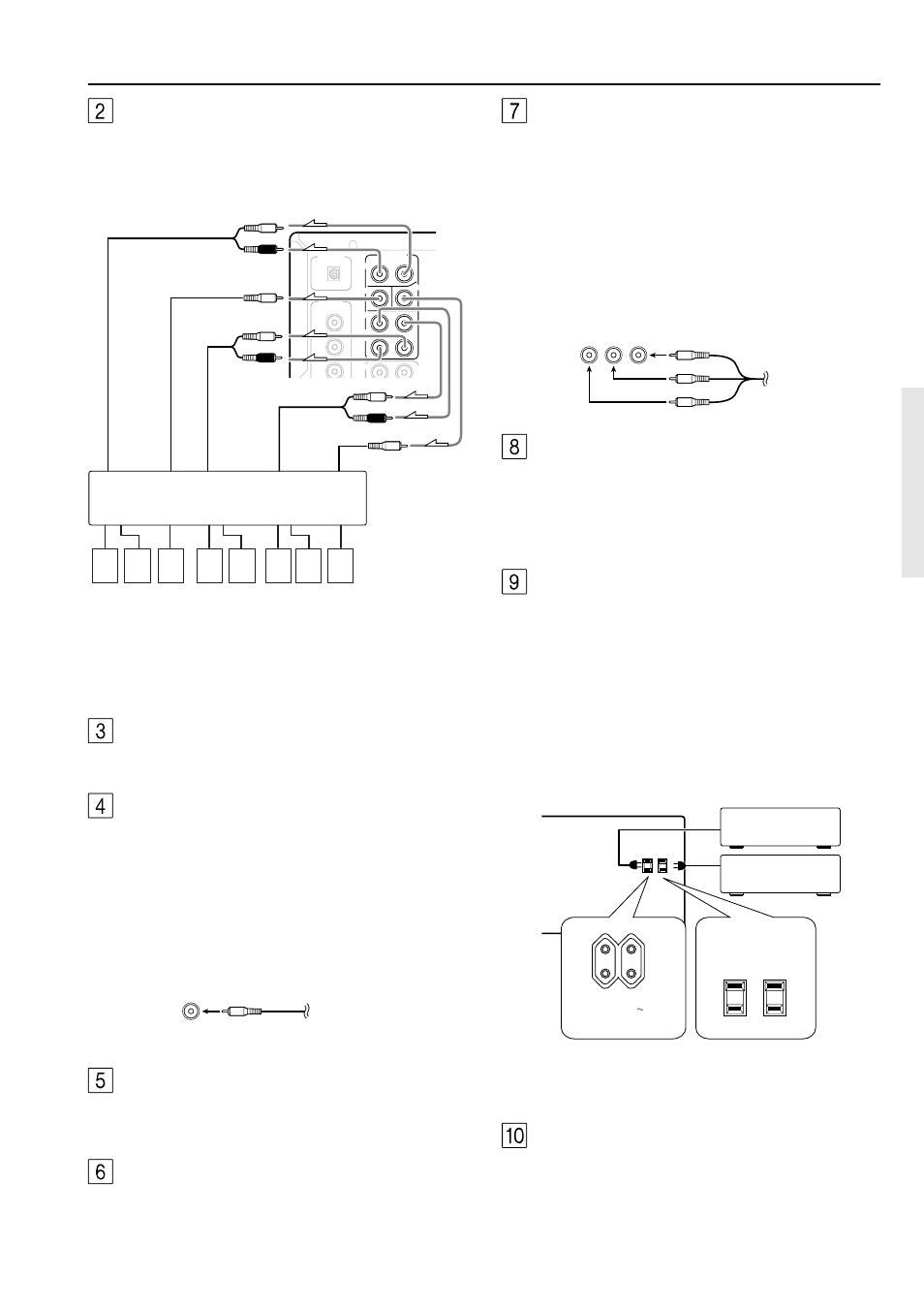
AUDIO IN/OUT
These are the analog audio inputs and outputs. There are eight audio
inputs and 3 audio outputs. The audio inputs and outputs require
RCA-type connectors.
• When connecting a VCR or other video component, make sure
you connect the audio and video leads together (i.e., both to
VIDEO 3).
• The PHONO (PH) input jacks on the TX-DS797 is designed for
use with turntables that use moving magnet cartridges.
Rear panel facilities
PRE OUT
These jacks are for connecting auxiliary power amplifier.
Using auxiliary power amplifiers allows you to listen at louder
volumes than with the TX-DS797 alone. If power amplifiers are
used, connect each speaker to the corresponding power amplifier.
Power amplifier
1. Front left speaker
2. Front right speaker
3. Subwoofer
4. Surround back left
speaker
MONITOR OUT
The monitor output includes both composite video and S video
configurations. This output is for connecting television monitors or
projectors.
ZONE 2 AUDIO/VIDEO OUT
Connect the device that will be used in the remote zone (Zone 2). For
more information regarding how to make the connections, refer to
“Connecting the remote zone (Zone 2) speakers” on page 21.
SPEAKERS
Six terminals are provided for the front left, front right, front center,
surround left, surround right, and surround back speakers. Speaker
outputs are compatible with banana plug connectors (other than
European models).
AC OUTLETS
The TX-DS797 is supplied with AC mains outlets for connecting the
power cords from other devices so that their power is supplied
through the TX-DS797. By doing this, you can use the STANDBY/
ON button on the TX-DS797 to turn on and off the connected
devices as well.
The shape, number, and total capacity of the AC outlets may
differ depending on the area of purchase.
Caution:
Make sure that the total capacity of the other components connected
to this unit does not exceed the capacity that is printed on the rear
panel (e.g., 120 watts).
5. Surround back right
speaker
6. Surround left speaker
7. Surround right speaker
8. Center speaker
Y P
B
P
R
RCA type
AC OUTLETS
AC 120 V 60 Hz
SWITCHED
TOTAL 120W 1A MAX.
AC OUTLETS
AC 230-240 V 50 Hz
SWITCHED
TOTAL 100 W MAX.
12V TRIGGER ZONE 2 terminal
When the TX-DS797 is in the ZONE 2 mode, this terminal outputs at
12 V/100 mA.
COMPONENT VIDEO INPUT/OUTPUT
If your DVD player or other device has component video
connectors, be sure to connect them to these component video
connectors on the TX-DS797. The TX-DS797 has two component
video input connectors to obtain the color information (Y, P
B
, P
R
)
directly from the recorded DVD signal or other video component
and one component video output connector to output it directly into
the matrix decoder of the display device. By sending the pure DVD
component video signal directly, the DVD signal forgoes the extra
processing that normally would degrade the image. The result is
vastly increased image quality, with incredibly lifelike colors and
crisp detail.
RCA type
European and some
Asian models
USA and Canadian
models