Omron C-series User Manual
Page 30
4-3
Section
Optical Remote I/O Systems
21
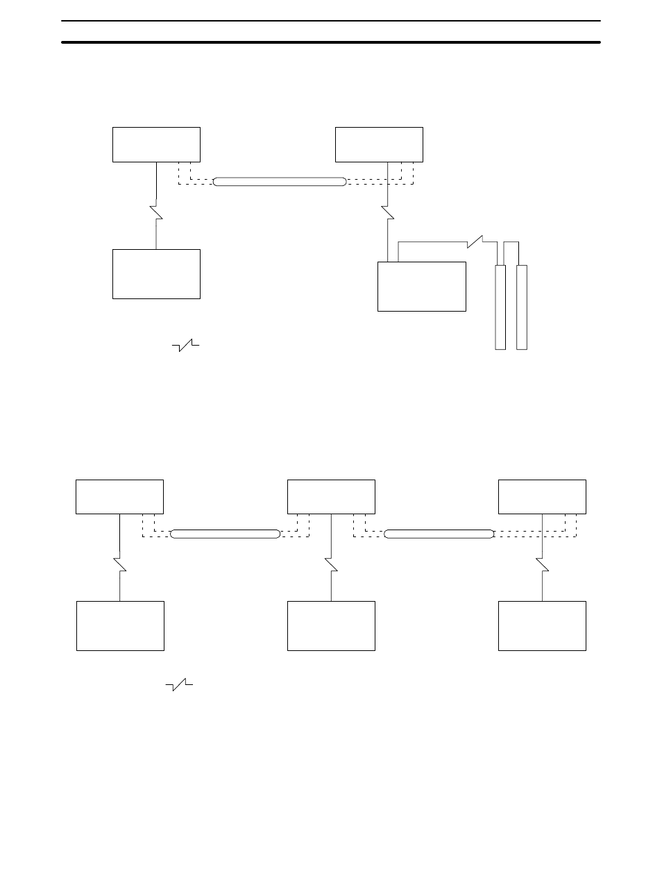
An Optical System with Optical Transmitting I/O Units can be connected with
crystal optical fiber cable (AGF) by using Link Adapter AL005-(P)E as shown be-
low:
Link Adapter
AL005-(P)E
CPU Rack with
Optical Master
Optical fiber (APF/PCF)
Link Adapter
AL005-(P)E
Optical Slave Rack
Optical Transmitting
I/O Units
Crystal optical fiber (AGF)
An Optical System with an I/O Link Unit can be connected with crystal optical
fiber cable by using Link Adapters AL005-(P)E and AL006-(P)E as shown be-
low:
Link Adapter
AL005-(P)E
CPU Rack with
Optical Master
Optical fiber (APF/PCF)
Link Adapter
AL006-(P)E
I/O Link Rack
Crystal optical fiber (AGF)
Link Adapter
AL005-(P)E
Crystal optical fiber (AGF)
Optical Slave Rack
A maximum of 8 Link Adapters can be used in this configuration.
Maximum total cable length is 10 km. Follow the instructions contained in
2-4
Crystal Optical Fiber Cable (AGF) for calculating the length of AGF cable.
Be sure to turn power off before disconnecting a cable. If an optical fiber
cable is disconnected while power is on in the Link Adapters and CPU, data
may be retained in the Slave.
Example 2
Example 3
Cable Length