Adhfi, Adnei, Adne – Omega Speaker Systems PCI-DAS1001 User Manual
Page 22: Ladful, 2 adc channel mux and control register badr1 + 2, Chl8-chl1, chh8-chh1, Gs[1:0, Sediff, Unibip
ADHFI
Status bit of ADC FIFO Half-Full interrupt. Used during REP INSW operations.
1 = Indicates an ADC Half-Full interrupt has been latched. FIFO has been filled
with more than 255 samples.
0 = Indicates an ADC Half-Full interrupt has not occurred. FIFO has not yet
exceeded 1/2 of its total capacity.
ADNEI
Status bit of ADC FIFO Not-Empty interrupt. Used to indicate ADC conversion
complete in single conversion applications.
1 = Indicates an ADC FIFO Not-Empty interrupt has been latched and that
one data word may be read from the FIFO.
0 = Indicates an ADC FIFO Not-Empty interrupt has not occurred. FIFO has
been cleared, read until empty or ADC conversion still in progress.
ADNE
Real-time status bit of ADC FIFO Not-Empty status signal.
1 = Indicates ADC FIFO has at least one word to be read.
0 = Indicates ADC FIFO is empty.
LADFUL
Status bit of ADC FIFO FULL status. This bit is latched.
1 = Indicates the ADC FIFO has exceeded full state. Data may have been lost.
0 = Indicates non-overflow condition of ADC FIFO.
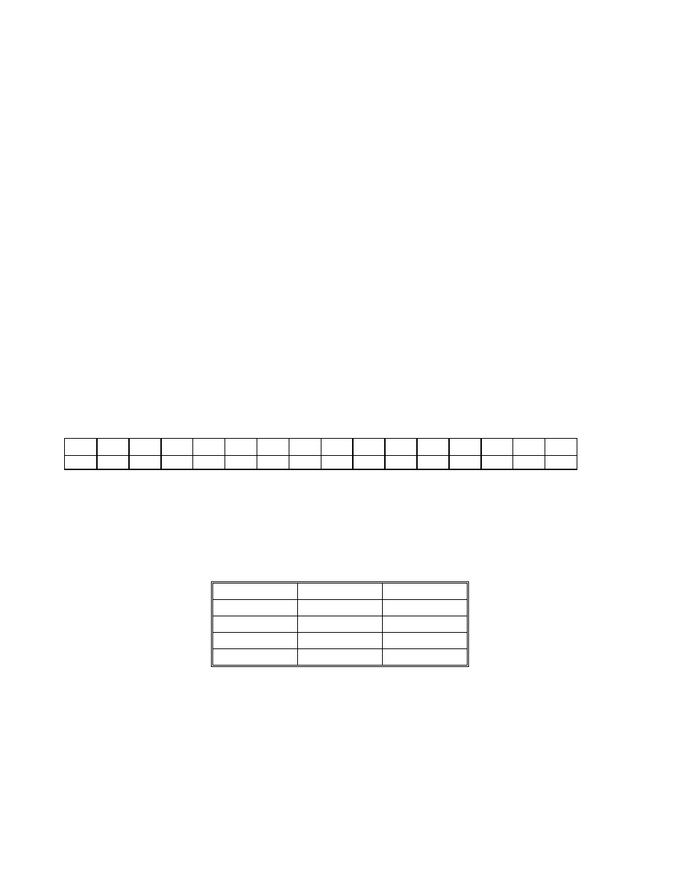
7.3.2 ADC CHANNEL MUX AND CONTROL REGISTER
BADR1 + 2
This register sets channel mux HI/LO limits, ADC gain, offset and pacer source.
A Read/Write register.
WRITE
CHL1
CHL2
CHL4
CHL8
CHH1
CHH2
CHH4
CHH8
GS0
GS1
SEDIFF
UNIBIP
ADPS0
ADPS1
-
-
0
1
2
3
4
5
6
7
8
9
10
11
12
13
14
15
CHL8-CHL1, CHH8-CHH1
When these bits are written, the analog input multiplexers are set to the channel specified by CHL8-CHL1. After each
conversion, the input multiplexers increment to the next channel, reloading to the "CHL" start channel after the "CHH"
stop channel is reached. LO and HI channels are the decode of the 4-bit binary patterns.
GS[1:0]
These bits determine the ADC range as indicated below.
1.25V
1
1
2.5V
0
1
5V
1
0
10V
0
0
Range
GS0
GS1
SEDIFF
Selects measurement configuration for the Analog Front-End.
1 = Analog Front-End in Single-Ended Mode. This mode supports
up to 16 channels.
0 = Analog Front-End in Differential Mode. This mode supports
up to 8 channels.
UNIBIP
Selects offset configuration for the Analog Front-End.
1 = Analog Front-End Unipolar for selected range
0 = Analog Front-End Bipolar for selected range.
19