1 introduction – Omega Engineering DIGITAL INPUT/OUTPUT PCI-DIO96 User Manual
Page 4
1 INTRODUCTION
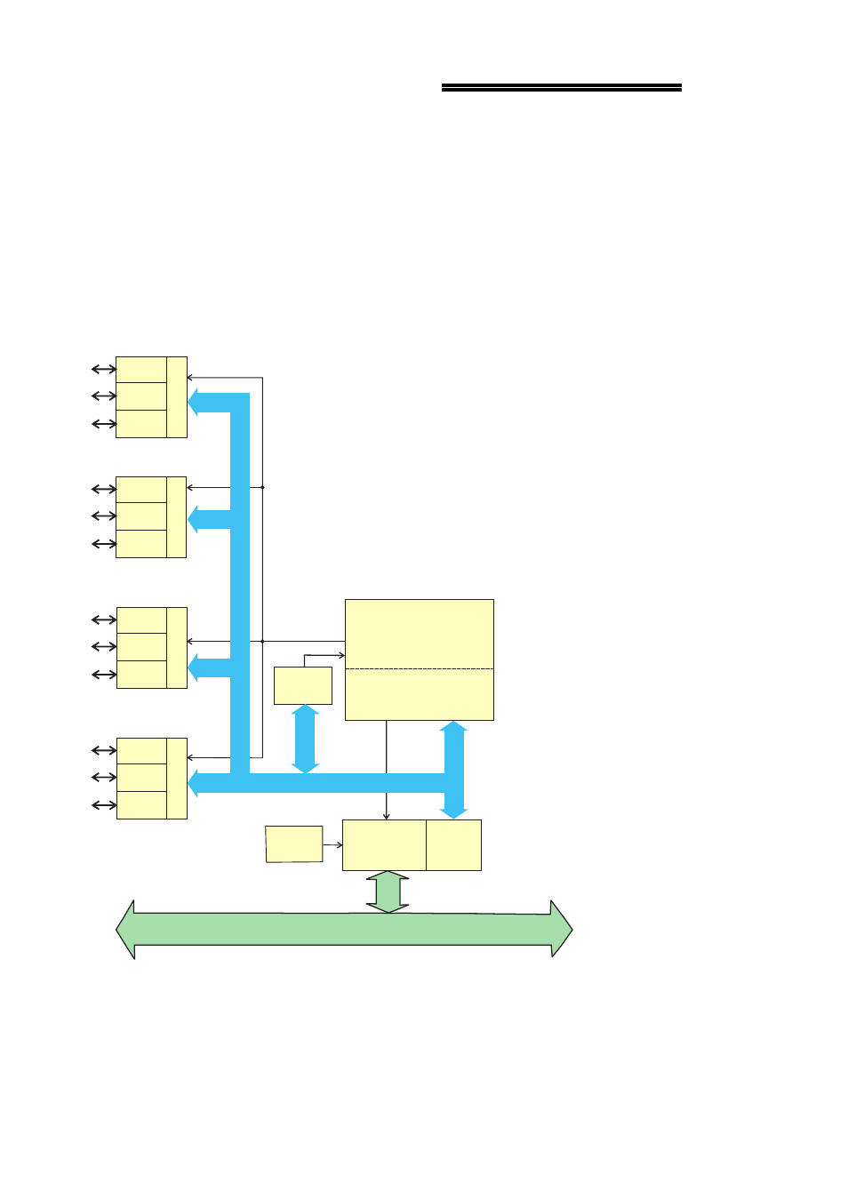
The PCI-DIO96 is a 96-bit line digital I/O board. The board provides the 96 bits in
four 24-bit groups. Each group provides an 8-bit port A and port B, as well as an
8-bit port C that can be split into independent 4-bit port C-HI and a 4-bit port C-LO.
See Figure 1-1 below.
On power up and reset, all I/O bits are set to input mode. If you are using the board
to control items that must be OFF on reset, you will need to install pull-down
resistors. Provisions have been made on the board to allow users to quickly and
easily install SIP resistor networks in either pull-up or pull-down configurations.
Figure 1-1. PCI-DIO96 Block Diagram
1
PCI-DIO96
Block Diagram
PCI BUS (5V, 32-BIT, 33MHZ)
PCI
CONTROLLER BADR3
Boot
EEPROM
Control
Registers
Decode/Status
CONTROLLER FPGA and LOGIC
LOCAL BUS
CONTROL
BUS
Port A
Port B
Control
(7:0)
(7:0)
DIO Group 0
Port C
(7:0)
Port A
Port B
Control
(7:0)
(7:0)
DIO Group 1
Port C
(7:0)
Port A
Port B
Control
(7:0)
(7:0)
DIO Group 2
Port C
(7:0)
Port A
Port B
Control
(7:0)
(7:0)
DIO Group 3
Port C
(7:0)
PLX-9052
COUNTERS
82C54
INT.
82C55
82C55
82C55
82C55