Trouble shooting, Factory channel settings, Output connector pin assignment – Omega DPS3100 User Manual
Page 23
Page 22
1
2
3
4
6
5
7
8
9
10
11
12
13
14
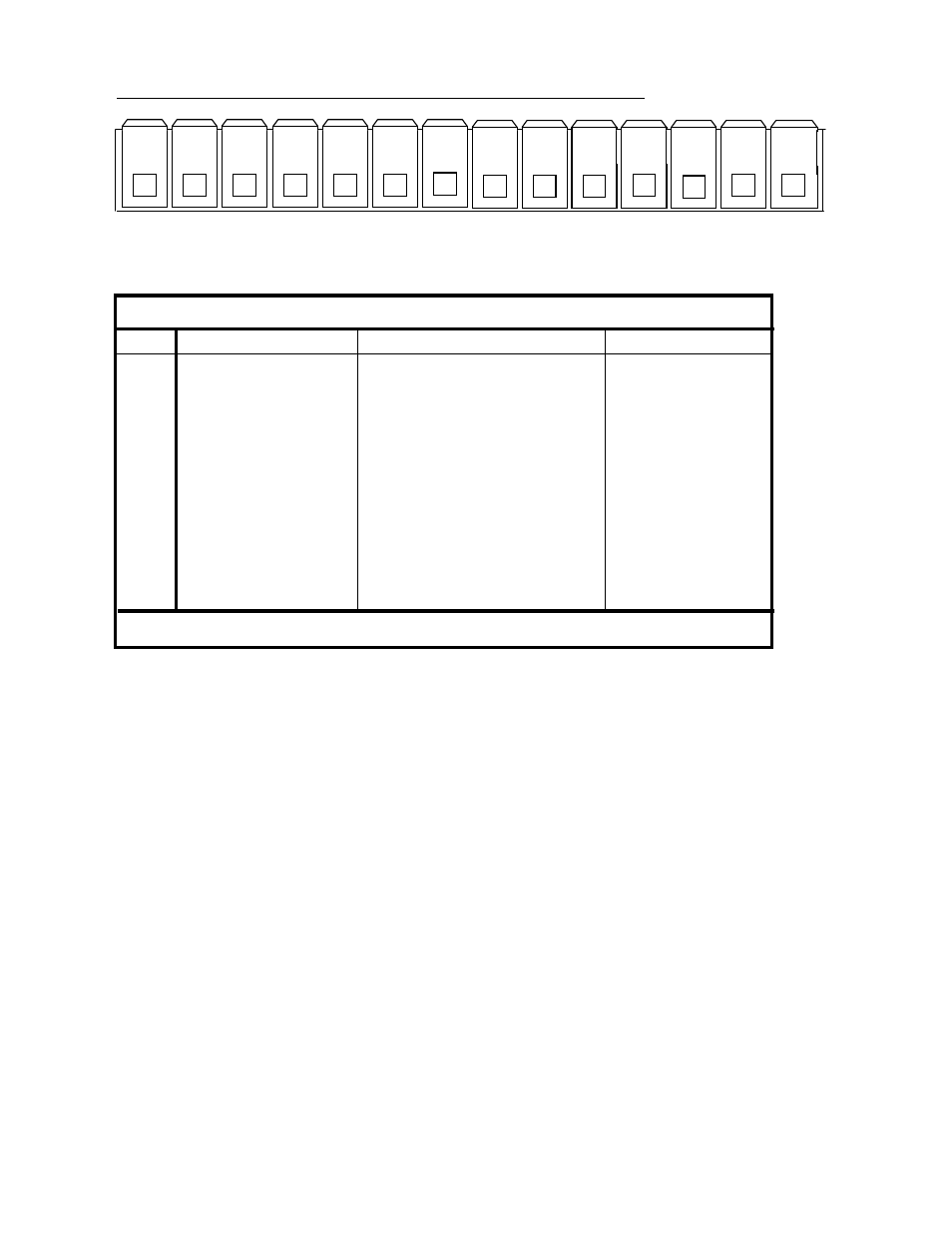
OUTPUT CONNECTOR PIN ASSIGNMENT
-
+
-
+
-
+
-
+
-
+
-
+
-
+
Table 1. DPS3000 Series Output Connector Pin Assignments
OUT-PUT CONNECTOR PIN ASSIGNMENTS
Pin # Signal
Relay Output
Open Collector
1 Channel #1 Limit
Common
Positive Output
2
Channel #1 Limit
Normally Open/Closed*
Negative Output
3
Channel #2 Limit
Common
Positive Output
4
Channel #2 Limit
Normally Open /Closed*
Negative Output
5
Channel #3 Limit
Common
Positive Output
6
Channel #3 Limit
Normally Open/Closed*
Negative Output
7
Channel #4 Limit
Common
Positive Output
8
Channel #4Limit
Normally Open/Closed*
Negative Output
9
Channel #5 Limit
Common
Positive Output
10
Channel #5 Limit
Normally Open/Closed*
Negative Output
11
Channel #6 Limit
Common
Positive Output
12 Channel #6 Limit
Normally Open/Closed*
Negative Output
13
Channel #7 Limit
Common
Positive Output
14
Channel #7 Limit
Normally Open/Closed*
Negative Output
* = Normally Open/Closed is user programmable (Look under Set-up)
NOTE: PROPER RATING, CONNECTION AND CORRECT ORIENTATION OF THE CONNECTOR IS
NECESSARY TO AVOID MALFUNCTION OR PERMANENT DAMAGE TO THE UNIT.