Eypad, Onnections, Ontroller – Russound CA-Series User Manual
Page 8
8
WIRING RUNS UP TO 100 FEET
For wiring runs of up to 100 feet in length, we recommend
the use of CAT-5 wire. It is inexpensive and color coded for
ease of installation. Due to the qualities of CAT-5 wire, when
using it for keypad control wire with the CA-Series, it is rec-
ommended to use the following color code for maximum
performance.
CAT-5
Number
Type
Brown/White
1
Ground
Brown
2
IR Signal
Green
3
12VDC+
Orange/White
4
Source Select
Orange
5
Source Select
Green/White
6
Channel Select
Blue/White
7
Volume
Blue
8
Balance
WIRING RUNS FROM 100-200 FEET
For wiring runs exceeding 100 feet and extending up to 200
feet, we recommend the use of 8-conductor 22 AWG strand-
ed wire such as Russound MCW2418.
If using 22 AWG wire, the order in which you wire is not
important as long as you wire in the same order at both the
CA unit as well as the keypad. Use List 5 (below) to write
down the wire you use for each pin number.
NOTE: Wiring runs longer than 200 feet are not recommend-
ed for the CA-Series Keypads.
List 5 –Wire color should be written below.
Pin 1 _______________ Pin 2 _______________
Pin 3 _______________ Pin 4 _______________
Pin 5 _______________ Pin 6 _______________
Pin 7 _______________ Pin 8 _______________
K
EYPAD
C
ONNECTIONS
A
T
C
ONTROLLER
I
NPUT
F
ROM
K
EYPADS
4
3
1 2 3 4 5 6 7 8
1 2 3 4 5 6 7 8
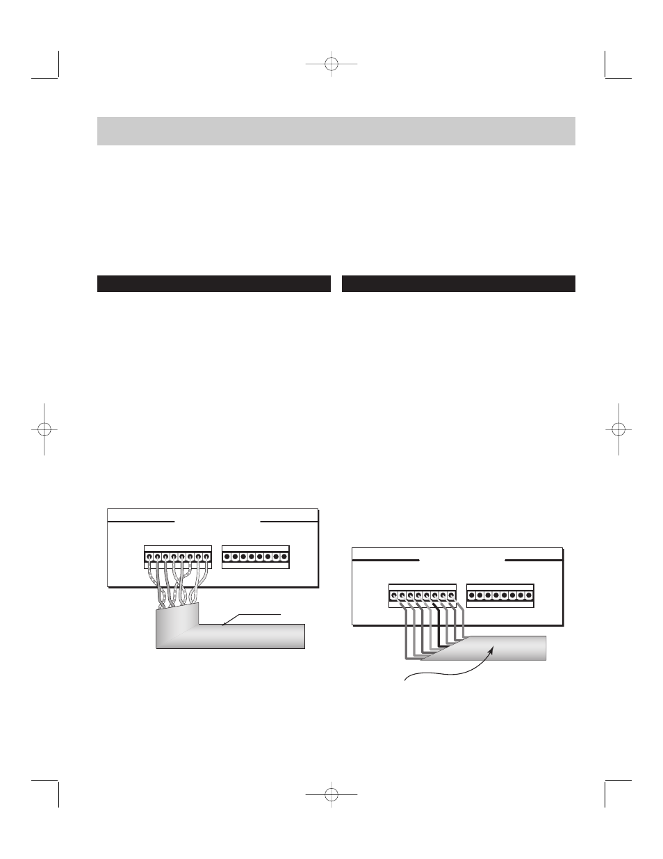
8 CONDUCTOR
22AWG STRANDED WIRE
I
NPUT
F
ROM
K
EYPADS
4
3
1 2 3 4 5 6 7 8
1 2 3 4 5 6 7 8
CAT-5 WIRE
BROWN
ORANGE
BLUE
GREEN
• Each keypad connection on the back panel of the CA-Series Master
Controller corresponds to the room / zone number chosen for your
speakers. Each zone operates independently, so it is very important to
connect the keypad to the correct zone keypad input.
• On List 4 (opposite) copy down the room name to the zone number
from List 3 on pg 6. NOTE: the keypad and the speakers in each room
must be hooked to the corresponding numbered zone.
• Remove the connector and strip 1/8" off each end of the wire insula-
tion. Connect each wire 1 thru 8 using a small jewelers screwdriver.
List 4 – Room names should be written below.
Zone 1 _________________
Zone 2 _________________
Zone 3 _________________
Zone 4 _________________
Figure 9 – Connections with CAT-5 wire
Figure 10 – Connections with 22AWG wire
CA-Series manual R6 10/17/01 1:50 PM Page 8