Anel, Onnections, Source input connections – Russound CA-Series User Manual
Page 6: Speaker connections
6
SOURCE INPUT CONNECTIONS
Your source inputs are located at the top left corner of the
back panel. Although the source input names are silk
screened on the back of the CA, these names are for refer-
ence only. Any type of source equipment can be connected
to any input. Connect each source output, left and right,
using quality signal cables / patch cables. Label each cable
the name of your source and the input number of the CA
you have selected. Repeat until all sources are connected.
List them down below.
List 1 – Source names should be written below
Input 1 (TUNER) ____________ Input 2 (CD) ____________
Input 3 (TAPE) ____________ Input 4 (AUX) ____________
SPEAKER CONNECTIONS
Each speaker connection on the back panel corresponds to
one room/zone. Wire your speakers by first removing the
connector for the chosen zone. Using wire strippers, strip
back 1/4" of the end of the wire. Insert the proper polarity,
left + to left +, left- to left- etc., until all wires are connect-
ed in each zone output. Label each wire with the room name
and zone number. Write down the room name to the zone
number below. Note: We recommend 8 Ohm minimum
speakers for each zone. However, speakers as low as 4 Ohm
can be safely used in up to two zones, if necessary.
List 2 – Wire color should be written below
(Color) Left + _______________ Left - _______________
Right + _______________ Right - _______________
List 3 – Room names should be written below
Zone 1 ________________ Zone 2 ________________
Zone 3 ________________ Zone 4 ________________
R
EAR
P
ANEL
C
ONNECTIONS
I
NPUT
F
ROM
K
EYPADS
6
5
4
3
2
1
O
UTPUT
T
O
8Ω S
PEAKERS
6
5
4
3
2
1
T
UNER
CD
T
APE
A
UX
R
L
100 mA
8
7
6
5
4
3
2
1
8
7
6
5
4
3
2
1
8
7
6
5
4
3
2
1
8
7
6
5
4
3
2
1
8
7
6
5
4
3
2
1
8
7
6
5
4
3
2
1
CA6.4
NEWMARKET, NH U.S.A.
W
ARNING
: S
HOCK
H
AZARD
–
D
O
N
OT
O
PEN
A
VIS
: R
ISQUE
D
E
C
HOC
E
LECTRIQUE
– N
ES
P
AS
O
UVRIR.
S
ERIAL
#
~110VAC
~220-240VAC
~50-60Hz
400W
~110VAC
~220-240VAC
VOLTAGE
110V
220-240V
FUSE
F4A
F2A
12V
T
RIG
IR
L
INK
IR R
EMOTE
O
UTPUT
4
3
2
PLUG-IN SEQUENCE
1
DESIGNED BY RUSSOUND
MADE IN KOREA
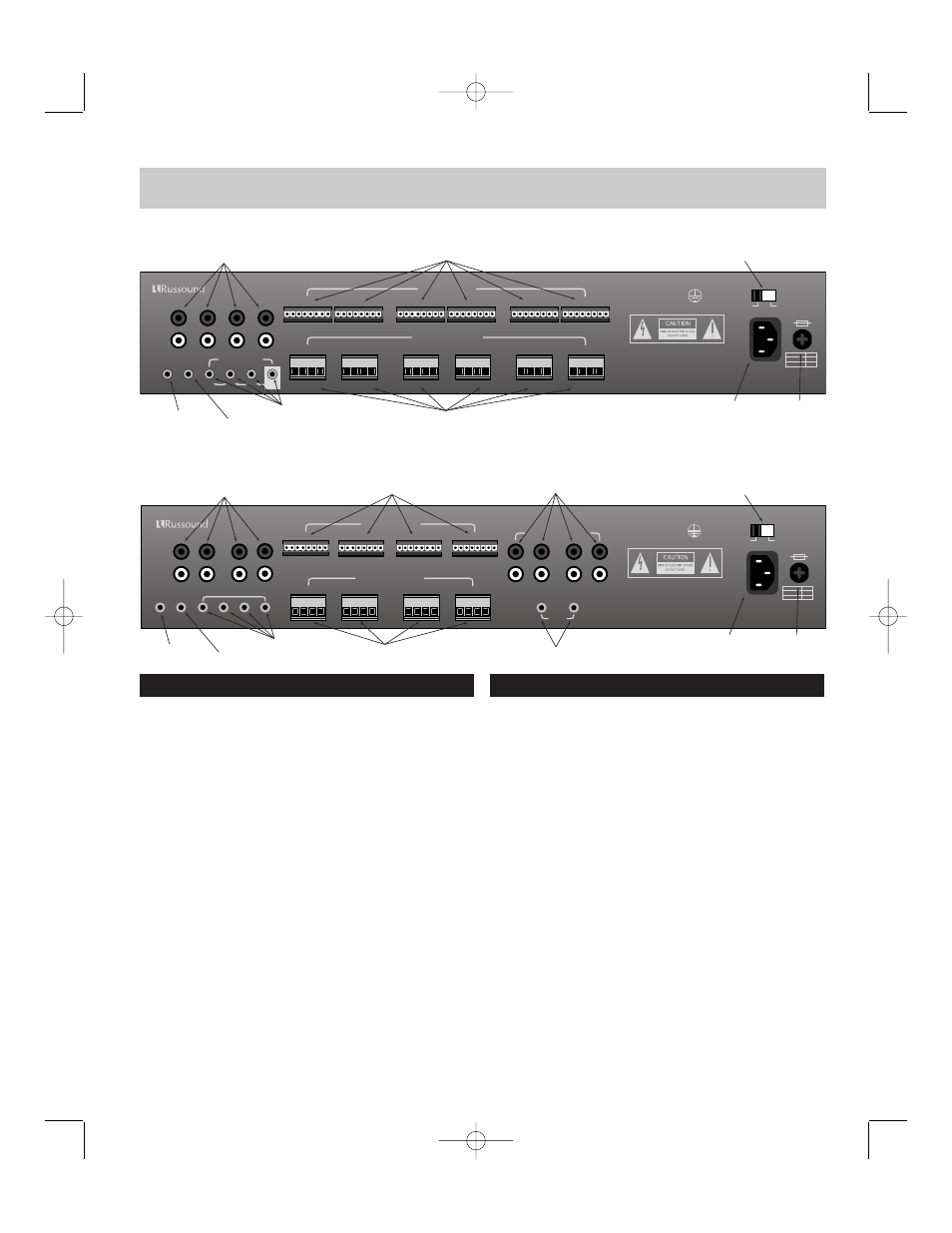
SOURCE INPUT
CONNECTIONS
KEYPAD ZONE INPUT
SPEAKER OUTPUT
CONNECTORS
12V TRIGGER
OUTPUT
IR LINK
EMITTER
OUTPUTS
VOLTAGE SELECTOR
SWITCH
AC110/240
INPUT
FUSE
HOLDER
W
ARNING
: S
HOCK
H
AZARD
–
D
O
N
OT
O
PEN
A
VIS
: R
ISQUE
D
E
C
HOC
E
LECTRIQUE
– N
ES
P
AS
O
UVRIR.
S
ERIAL
#
~110VAC
~220-240VAC
~50-60Hz
400W
~110VAC
~220-240VAC
VOLTAGE
110V
220-240V
FUSE
F4A
F2A
I
NPUT
F
ROM
K
EYPADS
4
3
2
1
O
UTPUT
T
O
8Ω S
PEAKERS
4
3
2
1
T
UNER
CD
T
APE
A
UX
R
L
R
L
1 2 3 4 5 6 7 8
1 2 3 4 5 6 7 8
1 2 3 4 5 6 7 8
1 2 3 4 5 6 7 8
IR R
EMOTE
O
UTPUT
4
3
2
1
USE #1 FIRST
CA4.4
NEWMARKET, NH U.S.A.
IR
L
INK
12V
T
RIG
100mA
4
3
2
1
Z
ONE
P
REAMP
O
UTPUTS
M
UTE
I
NPUT
D
OOR
B
ELL
T
ELE-
PHONE
SOURCE INPUT
CONNECTIONS
KEYPAD ZONE INPUT
ZONE PREAMP OUTPUTS
MUTE INPUTS
SPEAKER OUTPUT
CONNECTORS
12V TRIGGER
OUTPUT
IR LINK
EMITTER
OUTPUTS
VOLTAGE SELECTOR
SWITCH
AC110/240
INPUT
FUSE
HOLDER
Figure 3 - CA6.4 Rear Panel Connections
Figure 4 - CA4.4pi Rear Panel Connections
CA-Series manual R6 10/17/01 1:50 PM Page 6