Renesas M16C/6NK User Manual
Page 4
2. Connection
11. Fit the LCD module to J11 on the RSK, so it lies above J3. Ensure all the pins of the connector are correctly inserted in the socket.
12. Now connect the E8a to J8/E8 on the RSK using the ribbon cable.
13. Connect the E8a module to a spare USB port on the host PC.
The ‘Found New Hardware’ Wizard will appear. Please follow the steps below to install the drivers. Note that administrator privileges are required for a
Windows™ 2000/XP machine. Do not use the Windows Update option to locate the driver.
14. Verify the “Recommended” option is selected and click
15. If using Windows XP, skip to step 17; otherwise click
16. Click
17. Click
Note: The Windows driver signing dialog may be displayed. Please accept the driver to continue.
3. HEW
Workspace
HEW integrates various tools such as compiler, assembler, debugger and editor into a common graphical user interface. To learn more on how to use HEW,
open the HEW manual installed on your computer (Start Menu > All Programs > Renesas > High-performance Embedded Workshop > Manual Navigator).
18. Launch HEW from the Start Menu. (Start Menu > All Programs > Renesas > High-performance Embedded Workshop).
19. In the “Welcome” dialog box: Verify “Create New Workspace” is selected. Click
20. In the “New Project Workspace” dialog box: Set the “CPU Family” to “M16C”, and verify the “Tool chain” is set to “Renesas M16C Standard”. Select
“E8A_RSKM16C6NK” from the left hand pane.
21. Enter a name for the workspace. The project name will be automatically completed with the Workspace name. You can change this name to ‘Tutorial’ if
required. Click
22. On the “E8A_RSKM16C6NK – Step 1” window: Select “Tutorial” and click
23. On the “E8A_RSKM16C6NK – Step 2” window: Click
24. On the Project Generator Information window: Click
The project that is created has two configurations. The Release configuration can be used for the final release code version. The Debug configuration allows
modifications to the configuration for debugging.
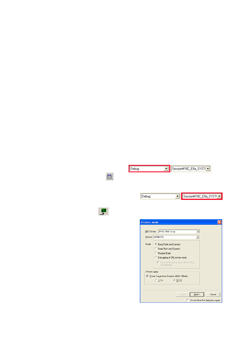
25. Select the Debug build configuration in the left hand drop down list on the tool bar.
26. Click on the ‘Build’ icon to compile, assemble and link the project.
4. Programming and Debug
27. Ensure the “SessionM16C_E8a_SYSTEM” session in the right hand drop down list on the
tool bar is selected.
28. Click the
29. The “Emulator Mode” wizard will be shown.
Select the correct MCU group (M16C/6NK) and device type (e.g. M306NKFJ for
RSKM16C6NK
)
Please note that the “Emulator mode” view shown here will only appear the FIRST
time you connect to the target within a project. On subsequent connections the
“Emulator setting” dialog will appear, please choose the same options to connect –
refer to the RSKM16C6NK Tutorial manual for details.
30. Select “Erase Flash and Connect”.
31. If the E8a is to provide the power to the RSK board, select “Power Target from Emulator”
and choose the “5.0V” option. Otherwise connect a 5V centre positive supply.
32. Click
D007214_11_S01_V04