Raymarine Radar Scanner User Manual
Page 32
24
Pathfinder Radar Scanners
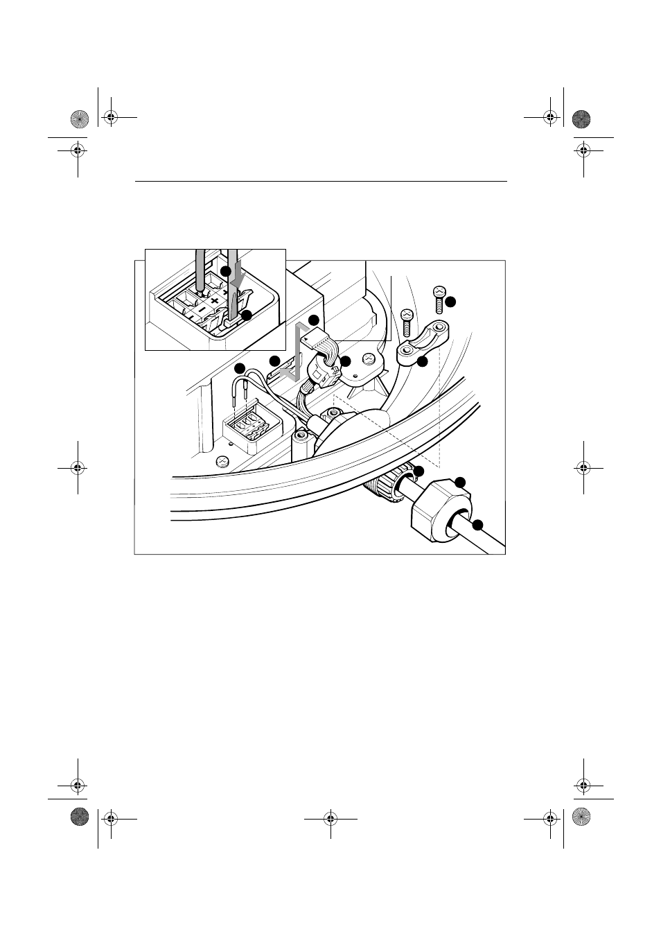
5. Referring to the following illustration, remove the securing nut
(1) from the watertight gland and grommet (2), where the inter-
unit cable (3) will enter the base.
1
11
1 Securing nut 2
22
2 Gland 3
33
3 Inter-unit cable 4
44
4 Eight-way plug 5
55
5 Eight-way socket 6
6
6
6 Power cores (2 or 4)
7
77
7 Terminal clamp 8
8
8
8 Screwdriver 9
9
9
9 Cable clamp 10
10
10
10 Cable clamp screws 11
11
11
11 Ferrite clamp
6. Slide the gland nut onto the inter-unit cable (3), and insert the
cable, still covered by its protective sleeve, through the gland into
the base.
7. Cut and remove the protective sleeve to expose the 8-way plug (4)
and power cores (6).
8. If the scanner is connected to an HSB Series Pathfinder Radar dis-
play, fit the ferrite clamp (11), supplied loose with the display
unit, as follows:
D3230-4
10
4
5
9
White wire
6
3
1
2
11
7
8
154_4.book Page 24 Wednesday, October 25, 2000 3:02 PM