Raypak B0109 User Manual
Page 20
CONNECTIONS - PLUMBING
20
The table below provides indicative pipe and pump sizes for typical installations
Model Pump
Branch
Size
Minimum Manifold Header
Size Required (mm)
UPS
Series
Speed inches mm
1
Unit
2
Units
3
Units
4
Units
109
20-60B
3 1 25 25 32 32 40
147
20-60B
3 1
25 20 32 32 40
PUMP SELECTION
In order to obtain the best possible water flow in the system a correctly sized pump must be installed. Refer to the
Flow Rate and Pressure Drop table below and allow for the system head pressure when sizing the pump.
The pump selected should provide a 10 to 20°C
temperature difference between the water heater inlet and outlet
when the water heater is at full fire.
Mechanical heating systems with multiple zones may require additional pump(s) refer to ‘Multi Pump Options’ on
page 28.
WATER FLOW RATE AND PRESSURE DROP
10°C Rise
15°C Rise
20°C Rise
Model l/sec kPa l/sec kPa l/sec kPa
109 0.5 5.0 0.4 4.0 0.3 3.0
147 0.8 5.0 0.5 3.0 0.4 3.0
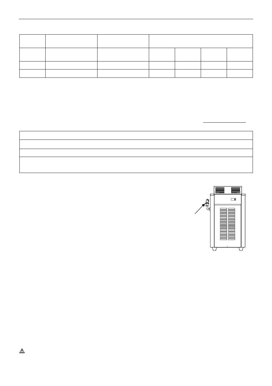
PRESSURE RELIEF VALVE
The pressure relief valve and elbow are shipped in a plastic bag inside the water heater.
The pressure relief valve must be fitted before the water heater is operated.
Fit the elbow supplied in the plastic bag to the connection on the inlet/outlet header then
screw the relief valve onto the other end of the elbow.
Seal the threads using Teflon tape, never hemp. A drain line must be
installed in accordance with AS/NZS 3500.4 to carry the discharge from
the valve to a suitable discharge point.
Relief Valve Pressure Rating
On/Off Models
850 kPa (125 psi)
Hi/Lo Models
310 kPa (45 psi)
When the water heater is connected to a storage cylinder for water heating applications, a correctly sized and
pressure rated TPR valve MUST be fitted to the storage cylinder.
NOTE:
Where a Hi/Lo water heater is used in a water heating application it will be necessary to replace the
310 kPa relief valve provided with the water heater with one rated at 850 kPa.
RELIEF VALVE DRAIN
A copper drain line must be fitted to the relief valve to carry the discharge clear of the water heater. Connect the
drain line to the relief valve using a disconnection union. The pipe work from the relief valve to the drain should be
as short as possible and fall all the way from the water heater with no restrictions. It should have no more than
three right angle bends in it. Use DN20 pipe.
The outlet of the drain line must be in such a position that flow out of the pipe can be easily seen (refer to
AS/NZS 3500.4) - but arranged so hot water discharge will not cause injury, damage or nuisance. The drain line
must discharge at an outlet or air break not more than 9 metres from the relief valve.
In locations where water pipes are prone to freezing, the drain line must be insulated and not exceed 300 mm in
length. In this instance, the drain line is to discharge into a tundish through an air gap of between 75 mm and
150 mm.
WARNING: The pressure relief valve on this water heater may discharge high temperature water under certain
conditions, it is strongly recommended the pipe work downstream of the relief valve be capable of carrying water
exceeding 93
°C. Failure to observe this precaution may result in damage to pipe work and property.
Pressure
Relief Valve