Protection on twisted-pair data ports, Micro-d 10/100basetx port pin configuration – RuggedCom M2100 User Manual
Page 18
2. Installation
RuggedCom® RuggedSwitch®
18
M2100 Installation Guide Rev 1.0
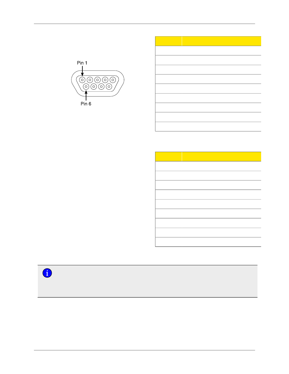
Figure 2.13. Micro-D 10/100BaseTX
Port Pin Configuration
Pin
Signal
1
TX+
2
No Connection
3
No Connection
4
No Connection
5
RX+
6
TX-
7
No Connection
8
No Connection
9
RX-
Table 2.3. Micro-D 10/100BaseTX Port Pin
Assignment
Figure 2.14. Micro-D 10/100/1000BaseTX
Port Pin Configuration
Pin
Signal
1
TP1+ (B+)
2
TP3+ (D+)
3
No Connection
4
TP2+ (C+)
5
TP0+ (A+)
6
TP1- (B-)
7
TP3- (D-)
8
TP2- (C-)
9
TP0- (A-)
Table 2.4. Micro-D 10/100/1000BaseTX Port Pin
Assignment
• For 10/100Base-TX ports: Pin 2 and Pin 7 are internally connected; Pin 4 and Pin 8 are
internally connected on the PCB board.
• For 10/100/1000Base-TX ports: Pin 3 and Pin 8 are internally connected on the PCB
board.
2.6.2. Protection on Twisted-Pair Data Ports
RuggedCom does not recommend the use of CAT-5 cabling of any length for critical real-time substation
automation applications. However, transient suppression circuitry is present on all copper ports to
protect against damage from electrical transients and to ensure IEC 61850-3 and IEEE 1613 Class 1
conformance. This means that during the transient event communications errors or interruptions may
occur but recovery is automatic.