Failsafe alarm relay wiring and specifications, Console port wiring, 16 2.5. console port wiring – RuggedCom M2100 User Manual
Page 16: Dielectric strength (hipot) testing, 16 2.10. failsafe alarm relay wiring
2. Installation
RuggedCom® RuggedSwitch®
16
M2100 Installation Guide Rev 1.0
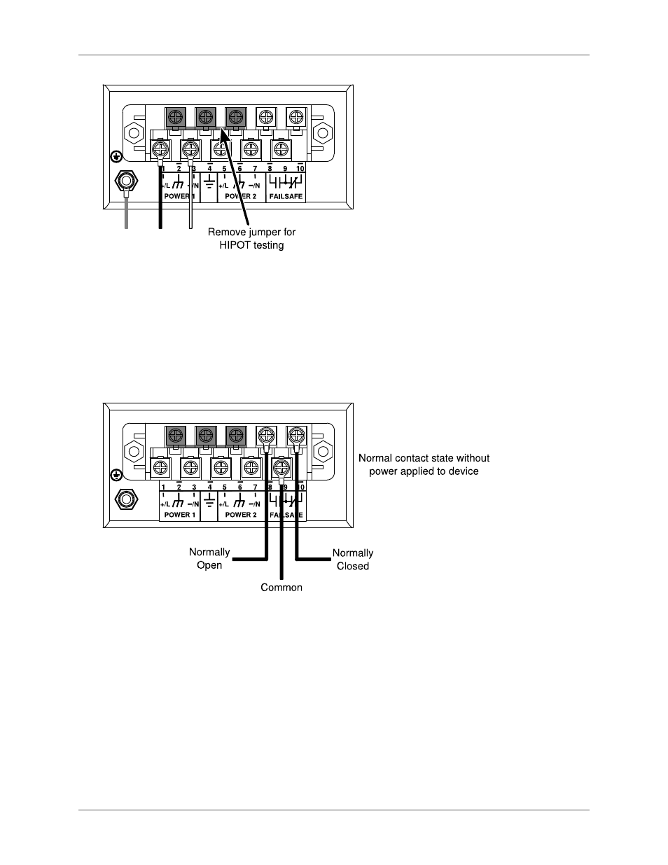
Figure 2.9. Dielectric Strength (HIPOT) Testing
2.4. Failsafe Alarm Relay Wiring and Specifications
The "Failsafe" output relay is provided to signal critical error conditions that may occur on the M2000
series switches. The contacts are energized upon power up of the unit and remain energized until a
critical error occurs. The proper relay connections are shown in
Figure 2.9, “Dielectric Strength (HIPOT)
. One common application for this output is to signal an alarm if a power failure or removal of
control power occurs.
Figure 2.10. Failsafe Alarm Relay Wiring
2.5. Console Port Wiring
A RS232 console port for configuration and management of the device is located on the LED display
module shown in
Figure 2.11, “Console port location on display board”
. This port is intended to be
a temporary connection during initial configuration or troubleshooting and allows for direct access
to the serial-based management console. The connection is made using the DB9-Female to RJ45
console cable included in the device packaging shown in
Figure 2.12, “M2000 Console cable”
. Console
connection settings are: 57600 baud, no parity bits, 8 data bits, and 1 stop bit.