Connection procedure, External dimensions and a sample foot pattern, Connection procedure (see figure 3) – Renesas Converter Board M3T-FLX-144NSE User Manual
Page 5
(3/4)
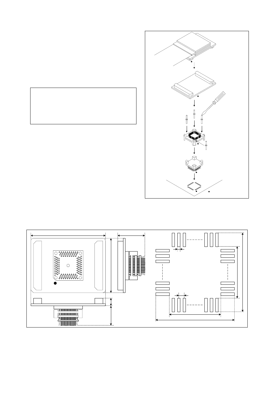
5. Connection Procedure (See Figure 3)
The procedure for connecting the M3T-FLX-144NSE is shown
below.
(1) Mount the NQPACK144SE on the target board.
(2) Attach the YQPACK144SE on the NQPACK144SE.
(3) Secure the four corners of the YQPACK144SE with the
YQ-GUIDE's.
● Do not use the screws included with the
YQPACK144SE for fixing the YQPACK144SE.
● The screwdriver included with the NQPACK144SE is
used for fixing the HQPACK144SE. Do not use if for
fixing the YQ-GUIDE's.
(4) Connect the probe of the emulation pod to the
M3T-FLX-144NSE.
(5) Attach the M3T-FLX-144NSE on the YQPACK144SE.
Figure 3 Connection procedure of the M3T-FLX-144NSE
6. External Dimensions and a Sample Foot Pattern
Figure 4 External dimensions and a sample foot pattern of the M3T-FLX-144NSE
Probe of emulation pod
M3T-FLX-144NSE
YQ-GUIDE (x4)
YQPACK144SE
NQPACK144SE
144-pin 0.4-mm-pitch
(144PFB-A) foot pattern
(1)
(2)
(3)
(5)
(4)
Be sure to use a
slotted screwdriver.
: No. 1 pin
Be sure to align the pins.
55.0
21.8
40
.0
0.225
0.4
15.1
19.1
15
.1
19
.1
Unit: mm
16.
5
40
a
40
b
1a
1b
CN2
M
3
T
-F
L
X
-1
4
4
N
SE R
E
V.
A
72
3
7
36
1
73
108
10
9
1
4
4
CN1
M
A
D
E
IN JAP
A
N
40
a
40
b
1a
1b
CN
1
CN
2
IC
1
5.
3