Connectors, Figure 2-2 . plasmaview vhd rear panel, 2. plasmaview vhd rear panel – Runco VP-5000VHDa User Manual
Page 18: Pre l iminar y
6
Vidikron PlasmaView VHD Installation/Operation Manual
PRE
L
IMINAR
Y
1.
DISPLAY STAND
Optional accessory for table-top installations.
2.
POWER BUTTON
Connects or disconnects the display panel from the AC power source.
3.
STANDBY/ON INDICATOR
- Lights green to indicate normal operation;
- Lights red to indicate that the PlasmaView VHD is in standby mode.
4.
REMOTE CONTROL SENSOR
Receives the signals from the remote control.
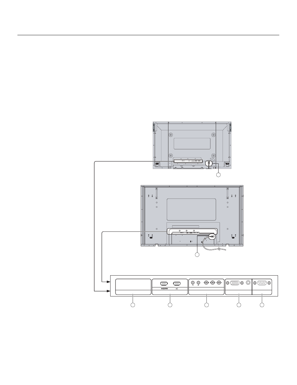
Connectors
Figure 2-2 shows the rear-panel connector locations on the PlasmaView VHD.
Figure 2-2. PlasmaView VHD Rear Panel
➤
SERIAL
PC IN
AUDIO
SLOT1
SLOT3
P
R
/C
R
/R
P
B
/C
B
/B
Y/G
AUDIO
R
L
COMPONENT/RGB IN
SLOT2
AV IN
A
B
VP-5000VHD
1
2
3
4
5
VP-6500VHD
6
6
NOTE:
Some PlasmaView VHD
models have a DVI-D input
board installed in SLOT 2.
This manual is related to the following products: