6 jupiter 20 module on adapter board, Figure 3-6 jupiter 20 adapter board – Navman LA000507 User Manual
Page 11
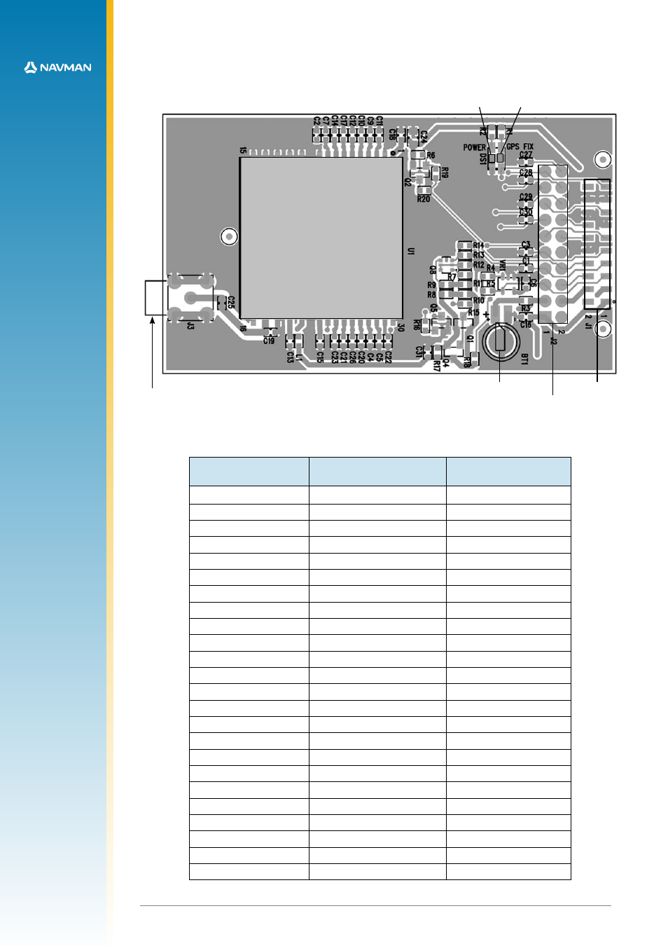
Jupiter 20 module
antenna
power LED
GPS fix LED
J1
J2
(not normally fitted)
RTC backup battery
(not normally fitted)
11
LA000510C © 2006 Navman NZ Ltd. All rights reserved. Proprietary information and specifications subject to change without notice.
3.6 Jupiter 20 module on adapter board
Figure 3-6 shows the adapter board with the positions of the connectors and indicators.
Figure 3-6 Jupiter 20 adapter board
Table 3-6 lists the pin configurations for the J1 and J2 connectors.
Jupiter function
J2 (2.54 mm pitch header)
pin no.
J1 (2 mm pitch header)
pin no.
V_ANT
1
1
VCC_RF
2
V_BATT
3
3
VDD
4
4
M_RST
5
5
GPIO3/GYRO IN
6
6
GPIO15/FR
7
7
BOOT
8
8
GPIO1/W TICKS
9
9
RFON
10
GND
10
TXA
11
11
RXA
12
12
GPIO5/SDI
13
GND
13
TXB
14
14
RXB
15
15
GPIO7/SCK
16
GND
17
16
GPIO6/SDO
18
GND
17
GND
18
1PPS
19
19
GPS_FIX/GPIO10
20
Table 3-6 Connections J1 (2 mm pitch header) and J2 (2.54 mm pitch header)
- 12 (90 pages)
- B10 (19 pages)
- 5505 (68 pages)
- iCN 620 (106 pages)
- JUPITER LA000267 (26 pages)
- F-Series (24 pages)
- F30 (24 pages)
- SmartS iCN530 (72 pages)
- N60i (2 pages)
- Sport Tool M300 (26 pages)
- GPS 3450 (8 pages)
- iCN 630 (8 pages)
- iCN 510 (92 pages)
- iCN 500 series (100 pages)
- F10 (90 pages)
- TRACKER950 (41 pages)
- iCN Series (8 pages)
- F25 (70 pages)
- PiN 570 (116 pages)
- Smart 2005 (68 pages)
- N-Series (144 pages)
- F20 (10 pages)
- LA000578A (17 pages)
- SmartST Professional (60 pages)
- Smart V3 (53 pages)
- ICN 330 (16 pages)
- 5380 (64 pages)
- iCN-700 Series (128 pages)
- TRACKER 5100 (42 pages)
- VHF 7200 (60 pages)
- Sport Tool W300 (26 pages)
- M-Nav 650 (84 pages)
- 3100 (16 pages)
- ICN 550 (72 pages)
- 5605 (68 pages)
- iCN 600series (41 pages)
- 2 (6 pages)
- GPS 4400 (8 pages)
- Tracker500/500i (44 pages)
- LA000508 (18 pages)
- tracker plotter TRACKER 5600 (42 pages)
- iCN700 (124 pages)
- S-Series (133 pages)
- 630 (8 pages)