7 serial port 2, 8 dr connector, 9 antenna connector – Navman LA000507 User Manual
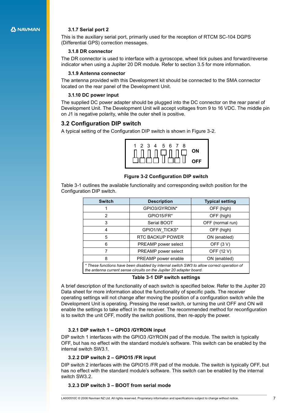
Page 7: 10 dc power input, 2 configuration dip switch, 1 dip switch 1 – gpio3 /gyroin input, 2 dip switch 2 – gpio15 /fr input, 3 dip switch 3 – boot from serial mode, Figure 3-2 configuration dip switch, Table 3-1 dip switch settings
 7 serial port 2, 8 dr connector, 9 antenna connector | 10 dc power input, 2 configuration dip switch, 1 dip switch 1 – gpio3 /gyroin input, 2 dip switch 2 – gpio15 /fr input, 3 dip switch 3 – boot from serial mode, Figure 3-2 configuration dip switch, Table 3-1 dip switch settings | Navman LA000507 User Manual | Page 7 / 16
 See also other documents in the category Navman GPS receiver:
- 12 (90 pages)
- B10 (19 pages)
- 5505 (68 pages)
- iCN 620 (106 pages)
- JUPITER LA000267 (26 pages)
- F-Series (24 pages)
- F30 (24 pages)
- SmartS iCN530 (72 pages)
- N60i (2 pages)
- Sport Tool M300 (26 pages)
- GPS 3450 (8 pages)
- iCN 630 (8 pages)
- iCN 510 (92 pages)
- iCN 500 series (100 pages)
- F10 (90 pages)
- TRACKER950 (41 pages)
- iCN Series (8 pages)
- F25 (70 pages)
- PiN 570 (116 pages)
- Smart 2005 (68 pages)
- N-Series (144 pages)
- F20 (10 pages)
- LA000578A (17 pages)
- SmartST Professional (60 pages)
- Smart V3 (53 pages)
- ICN 330 (16 pages)
- 5380 (64 pages)
- iCN-700 Series (128 pages)
- TRACKER 5100 (42 pages)
- VHF 7200 (60 pages)
- Sport Tool W300 (26 pages)
- M-Nav 650 (84 pages)
- 3100 (16 pages)
- ICN 550 (72 pages)
- 5605 (68 pages)
- iCN 600series (41 pages)
- 2 (6 pages)
- GPS 4400 (8 pages)
- Tracker500/500i (44 pages)
- LA000508 (18 pages)
- tracker plotter TRACKER 5600 (42 pages)
- iCN700 (124 pages)
- S-Series (133 pages)
- 630 (8 pages)