Fireplace vent connection, Gas installation – Napoleon Fireplaces BGD40-N User Manual
Page 21
21
W415-0299 / F / 01.16.07
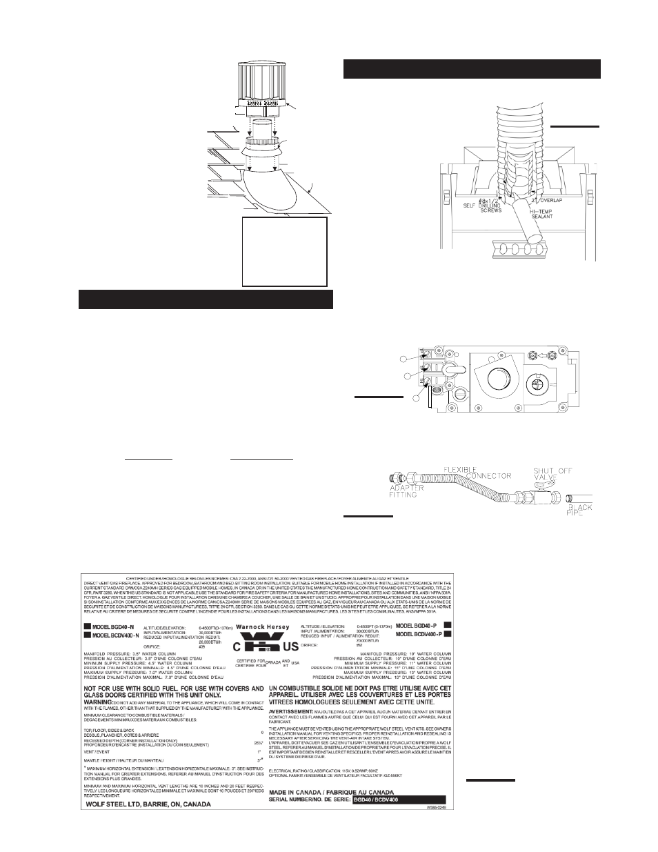
STORM COLLAR
FLASHING
CAULKING
WEATHER
SEALANT
2”
AIR INLET
BASE
FIGURE 39
1. Install the 5 inch diameter aluminum flexible liner to the
fireplace. Secure with 3 screws
and flat washers. Seal the joint
and screw holes using high
temp sealant (not supplied) or
Red RTV Silcone
may also be used in
this location.
2. Install the 8 inch
diameter aluminum
flexible liner to the
fireplace. Attach and
seal the joints.
For optimum per-
formance it is rec-
ommended that all horizontal runs have a ¼ inch rise
per foot.
6. Aligning the seams of the
terminal and air terminal
connector, place the terminal over
the air terminal connector making
sure the liner goes into the hole in
the terminal. Secure with the three
screws provided.
7. Apply a heavy bead of
weatherproof caulking 2
inches above the flashing.
Note: Maintain a minimum
2” space between the air
inlet base and the storm
collar. Install the storm collar
around the air terminal and slide
down to the caulking. Tighten to
ensure that a weather-tight seal
between the air terminal and the
collar is achieved.
FIREPLACE VENT CONNECTION
to the gas line and the fireplace gas valve. Seal and tighten
securely. An adapter fitting is required between the gas
valve and the copper tubing or flex connector.
Do not kink flexible connector.
5. Check for gas leaks by brushing on a soap and water
solution.
Do not use open flame.
6. Mark the appropriate boxes on the rating plate label to
indicate the model type.
1. Move the fireplace into position and secure to the floor
using #10 hex head screws (not supplied).
2. Route a 3/8" N.P.T. black iron gas line, 1/2" type-L
copper tubing or equivalent to the fireplace.
3. For ease of accessibility, an optional remote wall
switch or millivolt thermostat may be installed in a conven-
ient location. Route 2-strand (solid core) millivolt wire
through the electrical hole located at the bottom left side of
the unit.
The recommended maximum lead length depends on
wire size:
WIRE SIZE
MAX. LENGTH
14 gauge
100 feet
16 gauge
60 feet
18 gauge
40 feet
Do not connect either the wall switch, thermostat or
gas valve to electricity (110 volts).
Attach the two leads to terminals 1 and 3 located on the
gas valve.
4. Install the rigid black pipe, ½" type-L copper tubing or,
if local codes permit, a
3
/
8
" flex connector and shutoff valve
FIGURE 43
GAS INSTALLATION
FIGURE 44
P
I
PI
3
1
2
LOT
N O
L
O
T
H I
LO
FF O
FIGURE 42
Spacers are
attached to the inner
flex liner at
predetermined
intervals to maintain
a 1-1/4” air gap to
the outer flex liner.
These spacers must
not be removed.