Warning – Nordyne Downflow Direct Vent Forced Air Gas Oil Furnaces SERIES M1B User Manual
Page 19
19
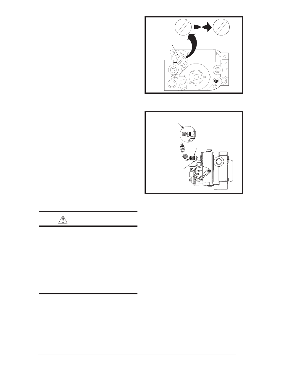
Figure 28. Honeywell Gas Valve
PRESSURE
REGULATOR
CAP
M11678
N
A
T N
A
T
L
P
L
P
N
A
T N
A
T
OR
OTHER SIDE
OF CAP
LP Gas
Configuration
Black Cover
Red
Natural Gas
Configuration
Figure 29. Robertshaw Gas Valve
High Altitude Conversion
High altitude conversion with this furnace
depends on the installation altitude and the
heating value of the gas. The installation of this
furnace at altitudes above 2,000 feet must meet
the requirements of the National Fuel Gas Code
or local jurisdiction. In Canada, the requirements
for high altitude are different and governed by
CGA B149.1. Please consult your local code
authority.
WARNING:
The reduction of input rating nec-
essary for high altitude installation
may only be accomplished with
factory supplied orifi ces. Do not
attempt to drill out orifi ces in the
fi eld. Improperly drilled orifi ces
may cause fi re, explosion, carbon
monoxide poisoning, personal
injury or death.
This furnace is shipped from the factory with
orifi ces and gas regulator settings for natural gas
operation at sea level altitudes. At 2000 feet, the
NFGC requires that this appliance be derated
4% for each 1000 feet of altitude. For example,
the input needs to be reduced 8% at 2,000 feet,
12% at 3,000 feet and etc. This deration is in
reference to the input rate and gas heating value
at sea level. See Table 12 (page 32).
6. For Honeywell gas valves with the regulator
converter (Figure 28, page 19):
a. Unscrew the pressure regulator cap and
check for the letters NAT or LP.
b. Invert the cap and tighten until snug.
7. For Robertshaw gas valves with the regulator
converter (Figure 29):
a. Remove the black cover and unscrew the
converter located on top of the gas valve.
b. Invert the converter: for LP the red ring will
be located at the bottom and the LP stamping
on the converter will appear right side up.
c. Screw converter back into the regulator,
hand tight plus 1/8 turn. Replace the black
cover on the converter top to protect the
threads.
8. Reassemble the burner assembly into the
furnace.
9. Reconnect the gas piping and electrical wires
to the gas valve.
10. Open the manual shut-off valve and follow
the Lighting and Operating instructions on
page 22.
Flue Gas Sampling
It may be necessary to take fl ue gas sampling
from oil and gas furnaces (M5S and M1B Series
Models) in order to check the performance after
furnace installation. A fl ue gas sample may
be taken from the heat exchanger, which is
located behind the hole of the top-front of blower
compartment.
1. Turn off all electric power to the appliance.
2. Remove the black plastic cap located above
the blower. Do not discard cap.
3. Drill a hole through the top of the blower
compartment. NOTE: Hole diameter should
be same size as sampling tube.
4. Insert sampling tube through the drilled hole
and into the heat exchanger.
5. After a complete check and adjustment
of furnace performance, seal the drilled
hole with a screw larger than the hole.
NOTE: Seal the screw threads with silicon
sealant - rated at least 500° F.
6. Plug the outside hole with the plastic cap
removed in step 3.