NCR S26 User Manual
Page 29
Configuring the System Board
NCR S26 Hot Plug Server User Guide
2-11
•
One shared slot (EISA or PCI)
•
256 KB flash ROM for easy system BIOS upgrade
•
System clock/calendar plus 8 KB extended CMOS RAM with battery
backup
•
Onboard AIC-7880 chip that supports one SCSI-2 port
•
50-pin Fast SCSI-2 and 68-pin Wide SCSI interfaces
•
Remote Diagnostic Management (RDM) module
•
I/O interfaces for one video slot, two serial ports, one parallel port,
peripheral drives, IDE drives, and one PS/2 keyboard and mouse
•
Power connector for 420-watt switching power supply
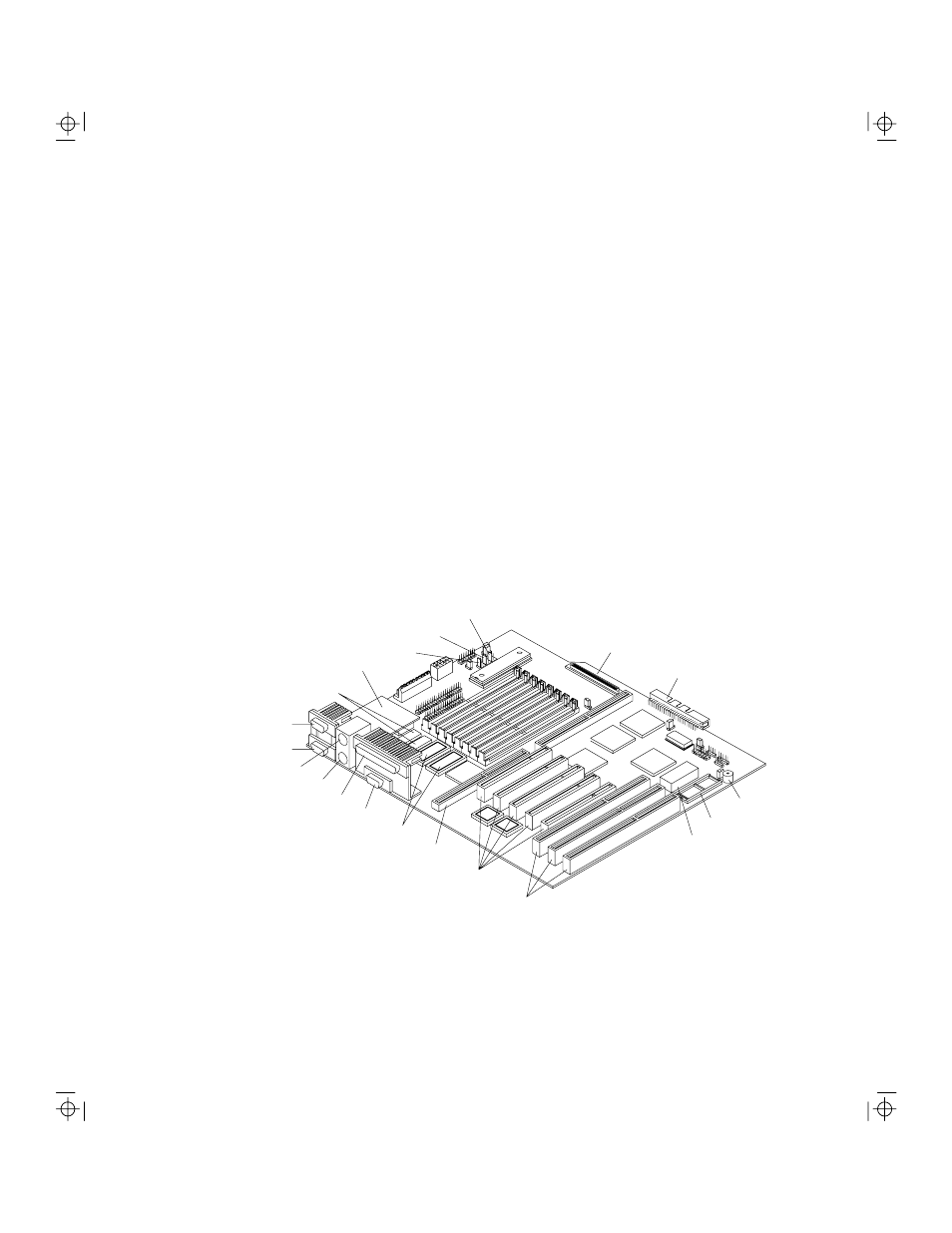
The figure below shows the location of the major components on the system
board.
Figure 2-7. System Board Layout
EISA slots
Buzzer
Flash ROM BIOS
Narrow SCSI connector
Real-time clock
Wide SCSI connector
PCI slots
CPU board slot
Keyboard port
Parallel port
Video port
Video upgrade sockets
Video RAM
Fan connector 3 (FA3)
Fan connector 2 (FA2)
Fan connector 1 (FA1)
RDM Module
Mouse port
COM1
COM2