Installing the so-dimm module – NEC 2000 Series User Manual
Page 80
4-10 Adding Expansion Devices
6.
Remove the screw securing the memory module panel and remove
the panel.
7.
Locate an empty module slot. If you need to remove one or both
modules, see “Removing a SO-DIMM Module” in the next section.
Before you install a SO-DIMM, reduce static
discharge by touching a metal part on the system unit.
8.
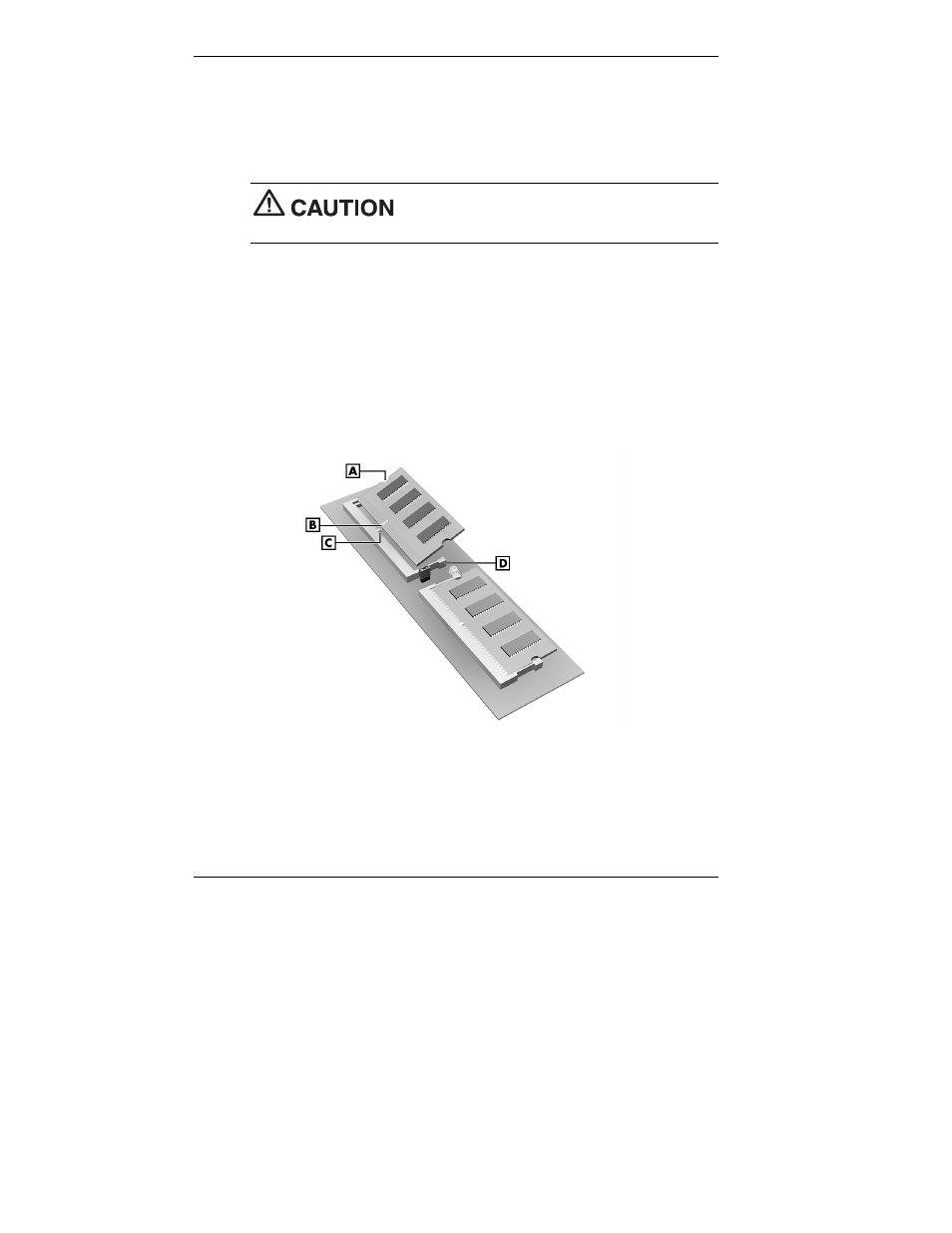
Install the SO-DIMM module as follows (see the following figure).
T
Align the notch in the module with the key in the empty slot.
T
Hold the module at a 45-degree angle and insert it into the slot.
T
Firmly push the module into the socket.
T
Press down on the edge of the module until the plastic retaining
clips snap into place.
Installing the SO-DIMM module
A – SO-DIMM Module
C – Socket Key
B – Notch
D – Plastic Retaining Clip (2)
9.
Install the SO-DIMM module panel and retaining screw.
10.
Plug in the AC adapter power cord and press the power switch.
- 20WGX (2 pages)
- FE791SB (41 pages)
- E500 (16 pages)
- XV29 Plus (33 pages)
- PX-42XR3A (8 pages)
- XP37 (38 pages)
- 42/50PD1 (64 pages)
- LCD1525X (30 pages)
- FE750 Plus (60 pages)
- FP2141SB (76 pages)
- 4205W (54 pages)
- AccuSync AS90M (4 pages)
- PX-50XM6A (203 pages)
- A500+TM (56 pages)
- ST-3215 (1 page)
- 42XM3 PX-42XM3A (8 pages)
- LCD1501 (118 pages)
- LCD4000 (38 pages)
- LCD4000 (37 pages)
- FP955 (68 pages)
- LCD22WV (2 pages)
- EA243WM (27 pages)
- E1100+ (56 pages)
- E1100+ (115 pages)
- EA221WM (2 pages)
- 175VXM (76 pages)
- SpectraViewII LCD2690W2-BK-SV (3 pages)
- LCD1550V (27 pages)
- PX-42VR5A (8 pages)
- LCD1525V (20 pages)
- LCD1530V (23 pages)
- 42VP4 (56 pages)
- A500 JC-1576VMB (92 pages)
- XV17+ (105 pages)
- A500 Plus (76 pages)
- PV40 (60 pages)
- XM29 Plus (40 pages)
- R 37 Xtra (38 pages)
- pmn (96 pages)
- AccuSync AS171 (18 pages)
- V520 (1 page)
- AccuSync LCD194WXM (78 pages)
- 60XC10 (41 pages)
- 1525M (33 pages)
- FE770/FE771 (18 pages)