Venting – Napoleon Fireplaces TORCH GT8N User Manual
Page 5
5
W415-0619 / A / 08.09.07
WARNING
DO NOT SUBSTITUTE MATERIALS.
USE CARE WHEN HANDLING GLASS COMPONENTS DO NOT STIKE, OR SLAM SHUT.
DO NOT OPERATE WITH BROKEN GLASS.
The glass is 3/16” ceramic glass available from your Napoleon® / Wolf Steel Ltd. dealer. Clean the glass after the fi rst 10
hours of operation with a recommended gas fi replace glass cleaner. Thereafter clean as required. DO NOT CLEAN GLASS
WHEN HOT! Do not use abrasive cleaners to clean plated parts. Buff lightly with a clean dry cloth. If the glass is not kept
clean permanent discolouration and / or blemishes may result.
CARE OF GLASS, AND PLATED PARTS
VENTING
VENTING LENGTHS
For safe and proper operation of the fi replace follow the venting instruction exactly.
The GT8N/P must be terminated horizontally only.
The vent connection to the fi replace can be viewed by removing the baffl e from the top, inside of the fi rebox.
Vent lengths that pass through unheated spaces (attics, garages, crawl spaces) should be insulated with the insulation
wrapped in a protective sleeve to minimize condensation.
Venting terminals shall not be recessed into a wall or siding.
Use only Wolf Steel Ltd. fl exible vent components with the Wolf Steel Ltd. GD179 termination kit.
With fl exible venting, in conjunction with the GD178 wall terminal kit, use either the 5 foot vent kit GDT5 or the 10 foot vent
kit GDT10. These kits allow for extended horizontal venting of the fi replace.
The maximum allowable vent length is 10’ feet using fl exible venting. The maximum number of allowable 3” vent
connections is one (excluding the fi replace and the air terminal connections).
For optimum fl ame appearance and fi replace performance, keep the vent length and number of elbows to a minimum.
The air terminal must remain unobstructed at all times. Examine the air terminal at least once a year to verify that it is
unobstructed and undamaged.
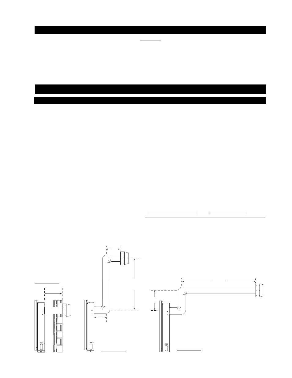
Horizontal runs may have a 0 inch rise per foot in all cases when venting as illustrated in
Figures 2a, 2b ,and 2c.
For optimum performance, it is recommended that all horizontal runs have a minimum ¼ inch rise per foot.
When venting, the horizontal run must be kept to a minimum of 4” inches or a maximum of 72”. If a 72”
horizontal run is required, the fi replace must have a minimum vertical rise immediately off the fi replace of 18”.
Figures 2a, 2b, and 2c.
Do not allow the inside liner to bunch up on horizontal runs and elbows. Keep it pulled tight. A
3
/
4
” air gap between
the inner and outer liner all around is required for safe operation.
Use fi restop spacer (W500-0358) when penetrating interior walls and ceilings.
FIGURE 2a
4” MIN.
24” MAX.
FIGURE 2b
84”
MAX.
8”
8”
MAXIMUM
VERITICAL
18”
MAXIMUM
HORIZONTAL
72” MAX.
FIGURE 2c